Laser cutting platform

A laser cutting, laser cutting machine technology, applied in laser welding equipment, welding/cutting auxiliary equipment, auxiliary welding equipment, etc., can solve the problem that the steel plate cannot be well supported, the steel plate cannot be effectively fixed, and is prone to offset and other problems, to achieve the effect of improving protection, low maintenance cost, and avoiding deformation or depression.

Active Publication Date: 2020-06-30
XINJIANG HUIXIANG LASER TECH
View PDF5 Cites 0 Cited by
  • Summary
  • Abstract
  • Description
  • Claims
  • Application Information

AI Technical Summary

Problems solved by technology

[0004] In order to solve the problem that the steel plate cannot be well supported when the laser beam is cut, and the steel plate cannot be effectively fixed on the cutting platform and is prone to offset, the present invention provides a laser cutting platform

Method used


Image

  • Laser cutting platform
  • Laser cutting platform
  • Laser cutting platform

Examples


Embodiment approach

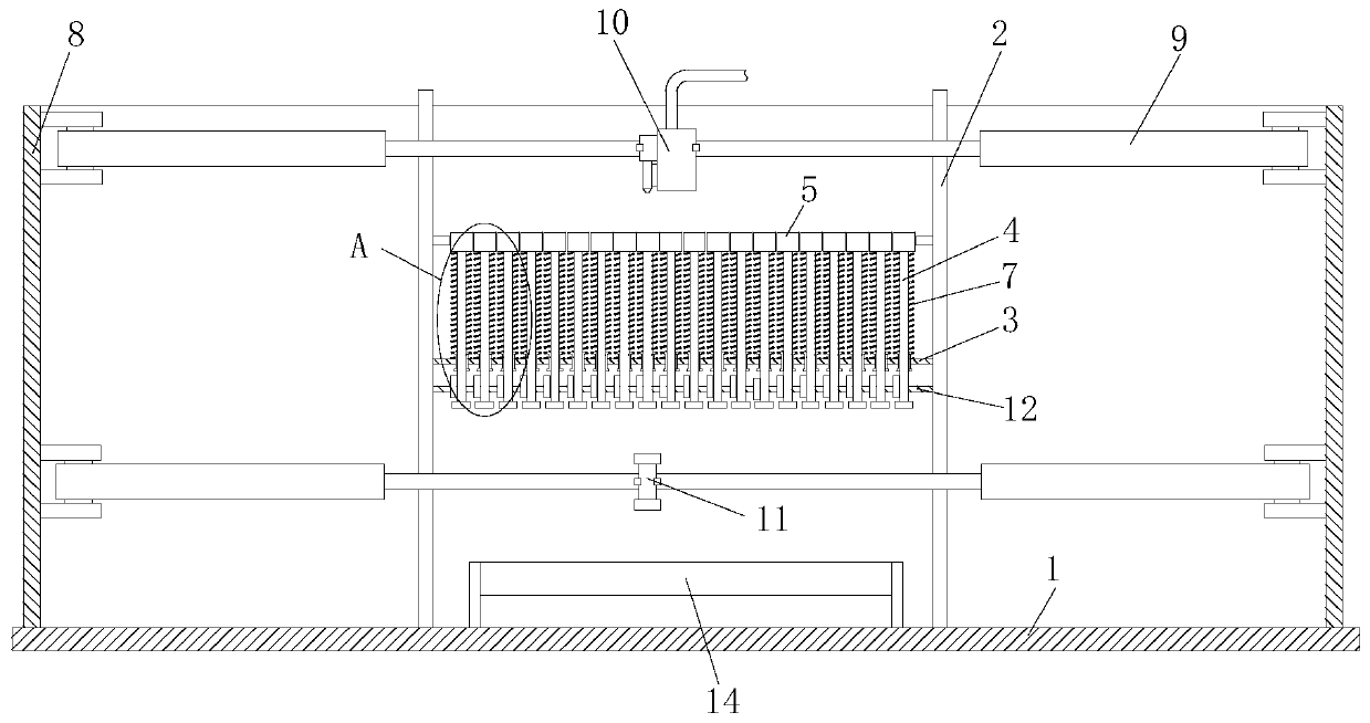
[0023] As an embodiment of the present invention, the displacement device 9 includes four servo electric cylinders, hinges are installed at both ends of the servo electric cylinders, and the hinge on one side is installed on the protective frame 8. The servo electric cylinder is respectively installed on the four frames of the protective frame 8 through hinges, and the hinge on the other side is installed on the side wall of the laser cutting machine body 10 or the No. 2 electromagnet 11. The cooperative work of the cylinders can make the laser cutting machine body 10 and the No. 2 electromagnet 11 reach any cutting position of the steel plate.

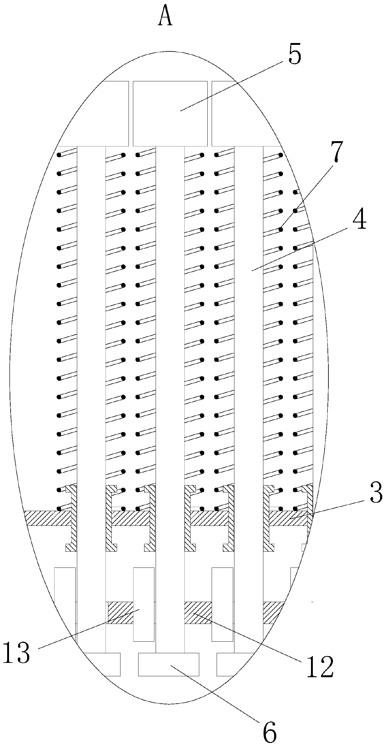
[0024] As an embodiment of the present invention, an auxiliary plate 12 is fixedly installed between the four columns 2, the auxiliary plate 12 is located below the mounting plate 3, and several mounting holes are provided on the auxiliary plate 12. No. three electromagnets 13 are fixedly installed on the side wall of the mounting hol...


PUM


Abstract

The invention relates to the technical field of laser cutting equipment, in particular to a laser cutting platform. The laser cutting platform comprises a base, four stand columns are fixedly installed on the base, an installing plate is fixedly installed among the four stand columns, a plurality of through holes are formed in the installing plate, and linear bearings are installed in the throughholes. First electromagnets are used for jointly forming a supporting face, after a steel plate is placed at a proper position, the plurality of first electromagnets firmly attract the steel plate soas to fix the steel plate, the problem of deviation of the steel plate is avoided, a second electromagnet downwards attract permanent magnets so as to enable the first electromagnets below a laser cutting machine body to be away from the to-be-cut steel plate, laser beams can be prevented from damaging the surfaces of the first electromagnets, the first electromagnets below a cutting point can bestretched downwards through the second electromagnet, the effect of heightening the steel plate is achieved, other areas except the cutting point are supported by the first electromagnets, the supporting performance is good, and the steel plate can be prevented from deforming or sinking.

Description

technical field [0001] The invention relates to the technical field of laser cutting equipment, in particular to a laser cutting platform. Background technique [0002] The laser cutting machine is a laser beam generated by a laser shock generator. The laser beam is concentrated in a small area through a lens and a mirror. The high concentration of energy can quickly heat the local area and melt the metal sheet to achieve the purpose of cutting. [0003] At present, in the process of cutting the steel plate, in order to avoid the laser beam from damaging the machine table, it is necessary to raise the steel plate, support the cut parts with several iron blocks with a certain flatness, and then cut them. However, in the process of cutting with the support block, when the supported area in the center of the cutting piece is cut off, the center of the entire cutting piece will lose support, which will cause the sag and deformation of the cutting piece, which will directly lead ...

Claims


Application Information

Patent Timeline
Patent Type & Authority Applications(China)
IPC IPC(8): B23K26/70B23K37/04B23K26/38
CPCB23K26/702B23K37/0408B23K26/38
Inventor 朱金娇黎晓勇黄黎明李晓兵孙传武李蓉许娇成
Owner XINJIANG HUIXIANG LASER TECH
Why Eureka
Try Eureka