Oil gas treatment system and treatment method

A technology for oil and gas treatment, oil and gas, applied in the direction of separation methods, chemical instruments and methods, steam condensation, etc., can solve problems such as inability to use combined processes, inability to provide absorbents, and influence on the stability and safety of catalytic oxidation operations. VOCs emission requirements, guarantee of safety and stability, and the effect of long-term safe and stable operation

Pending Publication Date: 2020-06-30
BAY ENVIRONMENTAL TECH BEIJING
View PDF0 Cites 4 Cited by
  • Summary
  • Abstract
  • Description
  • Claims
  • Application Information

AI Technical Summary

Problems solved by technology

However, for warehousing companies, since they are generally oil product temporary storage and transfer organizations and have no ownership over oil products and chemicals, they cannot provide absorbents required for conventional combined processes such as adsorption-absorption, absorption-membrane separation, etc. , so that the combined process combined with the absorption process cannot be used; if the three-stage condensation process or the condensation-adsorption combined process is adopted, the process stability is poor and the gas discharged after oil and gas treatment cannot meet the current non-methane total hydrocarbons less than 120mg in most areas. /m 3 Even 80mg/m 3 It needs to be further combined with the oxidation process to meet the more stringent environmental protection emission indicators. The oxidation process is generally a catalytic oxidation tre

Method used


Image

  • Oil gas treatment system and treatment method
  • Oil gas treatment system and treatment method
  • Oil gas treatment system and treatment method

Examples


Embodiment Construction

[0074] Hereinafter, the present invention will be described in more detail with reference to the accompanying drawings. In the various figures, identical elements are indicated with similar reference numerals. For the sake of clarity, various parts in the drawings have not been drawn to scale. Also, some well-known parts may not be shown in the drawings.

[0075] In the following, many specific details of the present invention are described, such as device structures, materials, dimensions, processing techniques and techniques, for a clearer understanding of the present invention. However, the invention may be practiced without these specific details, as will be understood by those skilled in the art.

[0076] Embodiments of the present invention will be specifically described below with reference to the accompanying drawings.

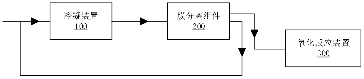
[0077] figure 1 An oil and gas treatment system according to a first embodiment of the present invention is shown. refer to figure 1 , the oil a...


PUM


Abstract

The invention discloses an oil gas treatment system and a treatment method, and the system comprises a condensation device which is used for carrying out condensation on collected oil gas, so as to obtain condensed liquid and non-condensable gas; a membrane separation assembly which is connected with the condensation device to receive the non-condensable gas, and is used for membrane separation treatment on the non-condensable gas to obtain intercepted oil gas and permeated oil gas with the organic matter concentration larger than that of the intercepted oil gas, wherein the permeated oil gasflows back to the condensation device; and an oxidation reaction device which is connected with the membrane separation assembly so as to receive the intercepted oil gas, and is used for performing oxidation reaction treatment on the intercepted oil gas so as to generate clean gas which can be discharged after reaching the standard. The oil gas treatment system can effectively solve the technicalproblems of strong dependence on the absorbent, substandard exhaust gas and high safety risk in the traditional oil gas treatment method.

Description

technical field [0001] The invention relates to the technical field of oil and gas recovery, and more specifically, to an oil and gas treatment system and treatment method. Background technique [0002] Because oil products contain a large amount of light hydrocarbon components, they are highly volatile, and will volatilize oil and gas during storage and transfer. The volatilization of oil and gas not only causes a large loss of oil products, but also pollutes the environment. Therefore, it is necessary to treat the volatilized oil and gas. Specifically, traditional methods such as adsorption, condensation, absorption, membrane separation and oxidation reaction can be used to recover oil and gas. . [0003] As the emission standards for volatile organic compounds (VOCs) become stricter, the VOCs content in the exhaust gas cannot meet the requirements of VOCs emissions after adsorption, condensation, absorption, membrane separation and oxidation reactions are used alone in c...

Claims


Application Information

Patent Timeline
IPC IPC(8): B01D5/00B01D53/00B01D53/22B01D53/86B01D53/72
CPCB01D53/002B01D53/228B01D53/8668
Inventor 锁晓婷魏巍
Owner BAY ENVIRONMENTAL TECH BEIJING
Why Eureka
Try Eureka