
Control method and device of permanent magnet synchronous motor and related assembly

A technology of permanent magnet synchronous motor and control method, which is applied in the direction of motor control, motor generator control, AC motor control, etc., can solve the problems of increasing hardware cost, burning brake resistance, high hardware cost, etc., and achieve improved stability and robustness performance, inhibit bus voltage rise, and ensure the effect of bus voltage

Inactive Publication Date: 2020-06-26
ZHEJIANG ZOBOW MECHANICAL & ELECTRICAL TECH
View PDF5 Cites 2 Cited by
  • Summary
  • Abstract
  • Description
  • Claims
  • Application Information

AI Technical Summary

Problems solved by technology

Energy-consumption braking is currently the most used method, that is, using an external braking resistor to release the excess bus energy. This method is simple to apply, but it increases the hardware cost additionally, and there is a risk of burning the braking resistor during continuous braking. ; Flux braking means that part of the energy is consumed inside the motor through the direct axis during braking. The commonly used method is the closed-loop PI control of the bus voltage. Compared with dynamic braking, this method saves hardware costs, but it is still unsolved. For the problem of braking, when the moment of inertia is large, it is necessary to perform air-slip protection, and braking cannot be achieved as soon as possible; feedback braking means that the bus energy is fed back to the power grid through the control of the frequency converter. The hardware cost of this method is too high, so it is not applicable for low power motors

Method used


Image

  • Control method and device of permanent magnet synchronous motor and related assembly
  • Control method and device of permanent magnet synchronous motor and related assembly
  • Control method and device of permanent magnet synchronous motor and related assembly

Examples


Embodiment Construction

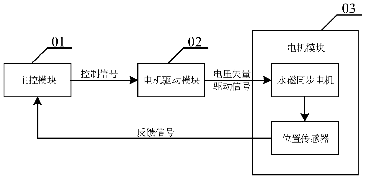
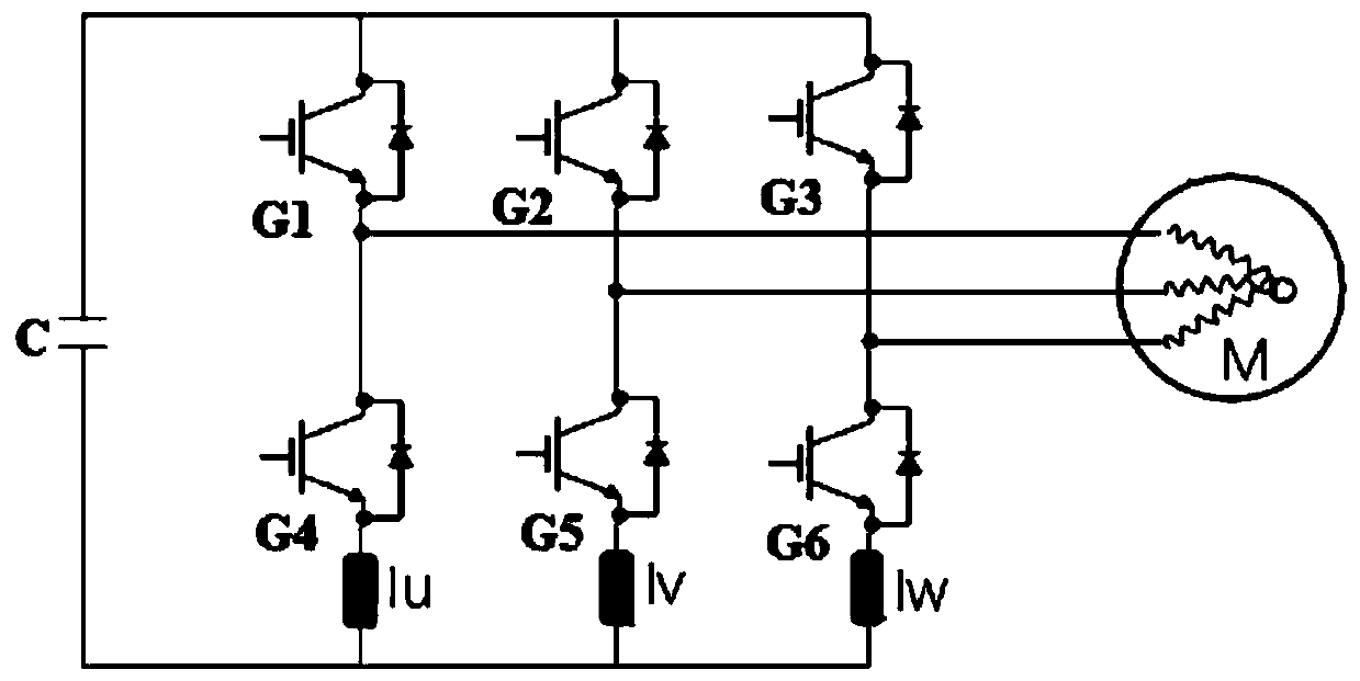
[0042] The core of this application is to provide a control method, device, electronic equipment and computer-readable storage medium for a permanent magnet synchronous motor. The software control scheme can effectively suppress the rise of the bus voltage when the motor is braking, and ensure the stability of the bus voltage. It can avoid the problem of affecting the braking control effect when the moment of inertia is too large, and ensure that fast braking can be achieved under any conditions, improving the stability and robustness of the system.

[0043] In order to make the purposes, technical solutions and advantages of the embodiments of the present application clearer, the technical solutions in the embodiments of the present application will be clearly and completely described below in conjunction with the drawings in the embodiments of the present application. Obviously, the described embodiments It is a part of the embodiments of this application, not all of them. B...


PUM


Abstract

The invention discloses a control method of a permanent magnet synchronous motor, and the method comprises the following steps: acquiring an actual bus voltage, and acquiring an initial electrical angle adjustment amount according to the actual bus voltage when the actual bus voltage meets a control condition; calculating a current electrical angle adjustment gradient, and obtaining an actual electrical angle adjustment amount by using the current electrical angle adjustment gradient and the initial electrical angle adjustment amount; and controlling the motor to operate through the current loop controller according to the actual electrical angle adjustment amount and the actual angle so as to suppress the rise of the bus voltage. By means of the scheme of software control, bus voltage rise during motor braking can be effectively restrained, bus voltage stability is guaranteed; meanwhile, the problem that the braking control effect is affected when rotational inertia is too large can be avoided, it is guaranteed that rapid braking can be achieved under any condition, and the stability and robustness of the system are improved. The invention further discloses a control device, electronic equipment and a computer readable storage medium, which have the above beneficial effects.

Description

technical field [0001] The present application relates to the field of permanent magnet synchronous motors, in particular to a control method, device and related components of permanent magnet synchronous motors. Background technique [0002] At present, the requirements of customers in the industrial sewing machine market are getting higher and higher. As the main component motor for driving sewing machines, most of the direct drive machines on the market currently use permanent magnet synchronous motors as the main shaft drive motors, and the control algorithm is also changed from the original three-phase brushless DC motor. Six-beat control, which is gradually upgraded to FOC (Field-Oriented Control, field-oriented vector control), makes the output torque of the motor stable, low noise, high efficiency, and has a faster dynamic response during operation. Its control idea is to implement double closed-loop control of speed loop and current loop on the permanent magnet sync...

Claims


Application Information

Patent Timeline
Patent Type & Authority Applications(China)
IPC IPC(8): H02P21/00H02P21/14H02P21/22H02P21/36H02P27/08H02P25/024
CPCH02P21/0003H02P21/14H02P27/085H02P2207/05H02P21/22H02P21/36H02P25/024
Inventor 龙涛万汉亮徐宗霖
Owner ZHEJIANG ZOBOW MECHANICAL & ELECTRICAL TECH
Learn More