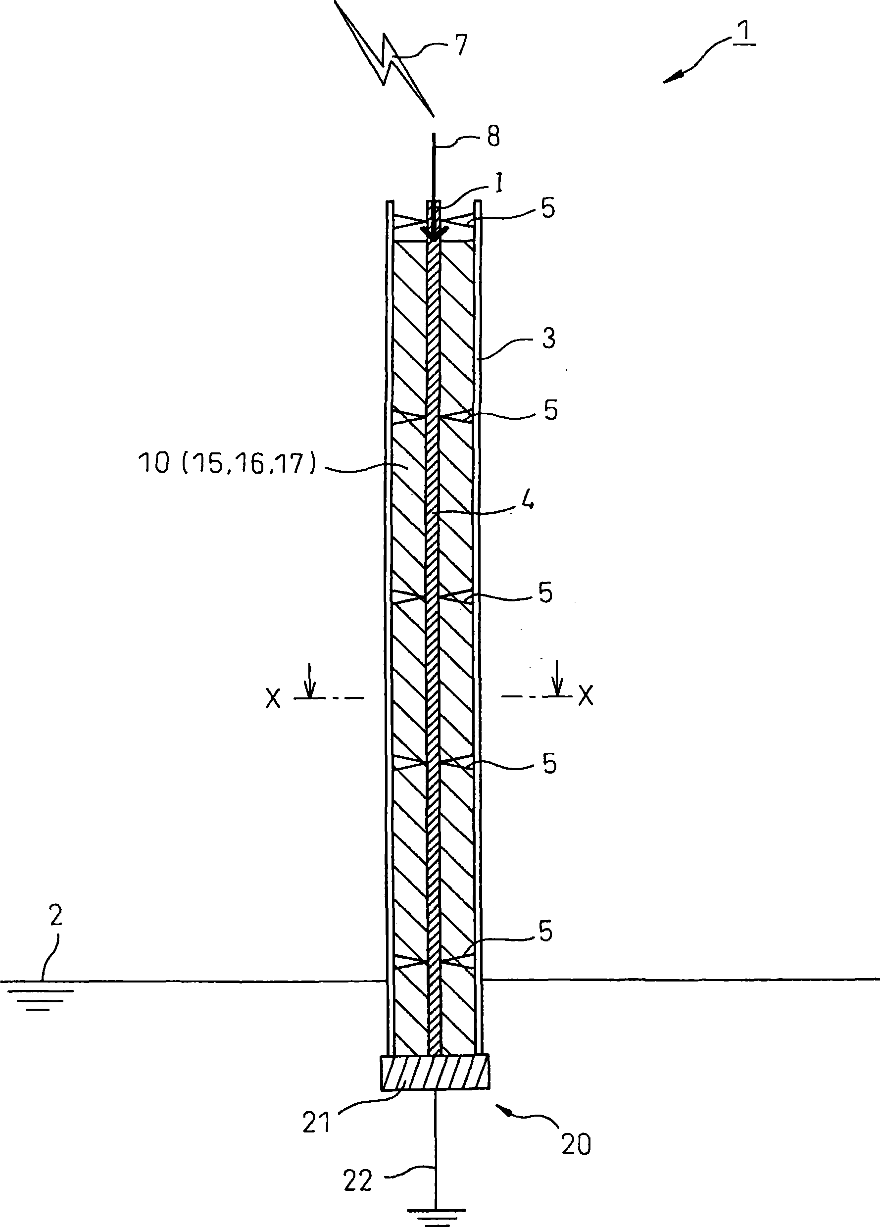
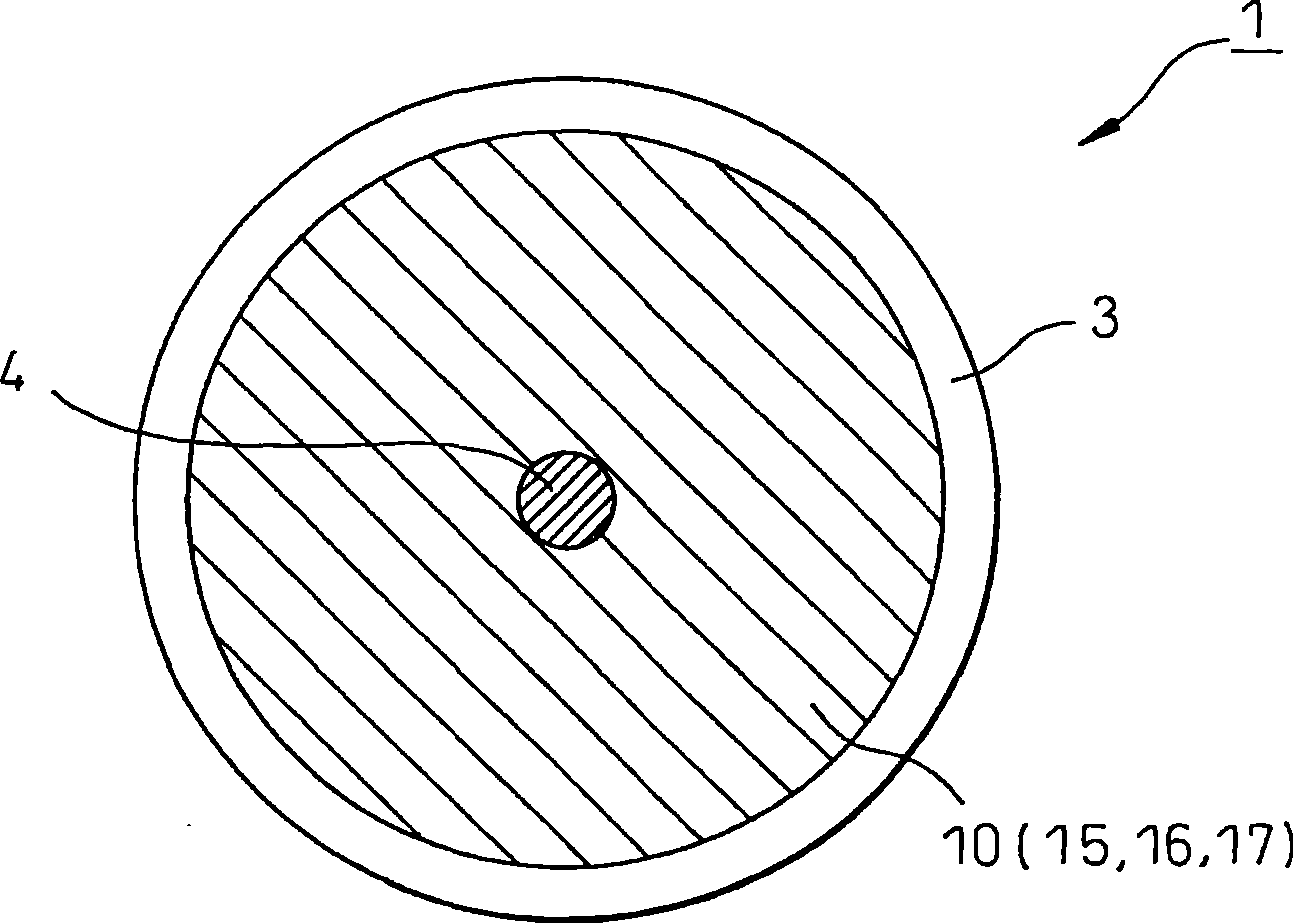
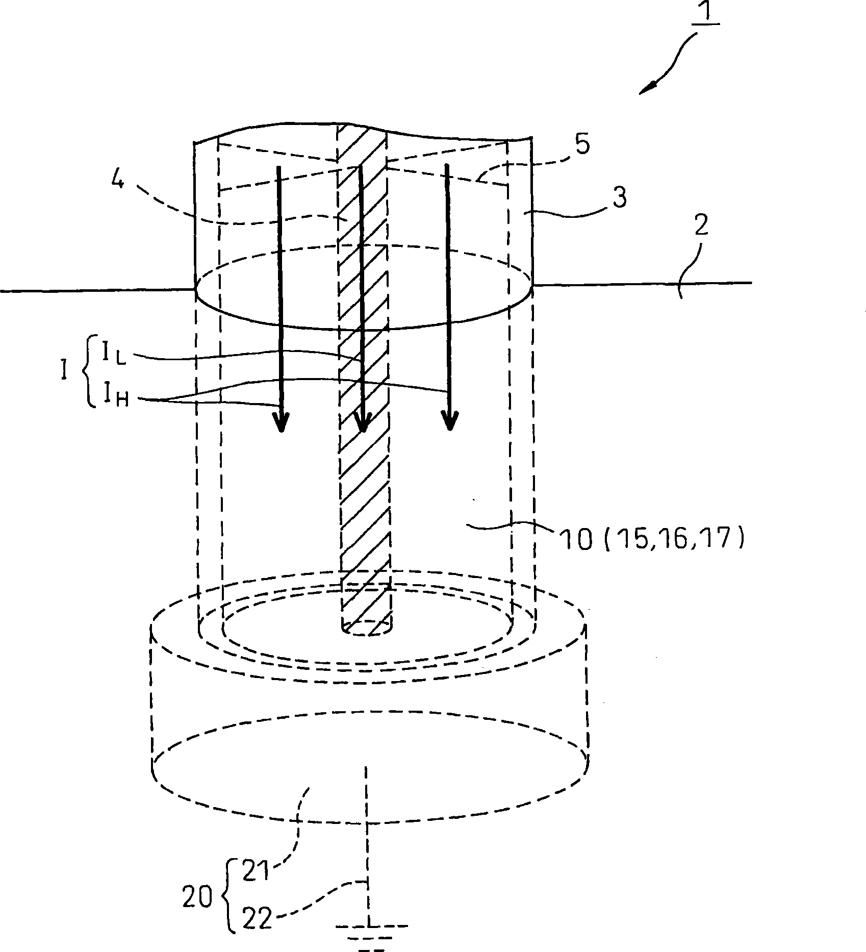
Lightning arrester, structure pillar having lightning arresting function, and reduction method of lightning surge voltage
A lightning protection device and surge voltage technology, applied in the direction of emergency protection circuit devices, circuit devices, emergency protection circuit devices for limiting overcurrent/overvoltage, etc. In order to avoid problems such as step voltage increase, it can reduce lightning disasters, suppress potential rise, and reduce grounding impedance.
- Summary
- Abstract
- Description
- Claims
- Application Information
AI Technical Summary
Problems solved by technology
Method used
Image
Examples
no. 2 Embodiment approach
[0074] According to the second embodiment of the present invention, the lightning protection device 1 is attached to existing equipment such as the signal machine 40, so compared with the case where the lightning protection device 1 is installed independently, the required strength and supporting structure can be reduced. Design constraints and the like make it easy to downsize and simplify, and the equipment cost and equipment space of the lightning arrester 1 can be reduced. The second embodiment of the present invention has the same effect as the first embodiment.
[0075] As a third embodiment of the present invention, as Figure 6 As shown, the present invention can also be applied to construction columns with lightning protection functions. Figure 6 It is a cross-sectional view in the vertical direction of the structural column 60 according to the embodiment of the present invention. Figure 7 yes Figure 6 The enlarged section view in Y—Y direction.
[0076] Such a...
Embodiment
[0123] Generally, the main frequency component of the lightning surge current is considered to be 10 KHz to 1 MHz. By applying the general transmission formula, the lightning protection device 1 and the ground electrode 101 related to the embodiment of the present invention are estimated, thereby utilizing the sine wave constant current method analysis to verify its validity.
[0124] As mentioned above, the lightning arrester 1 and the ground electrode 101 are regarded as Figure 4 , 12 The equivalent circuit of the lossy line shown, therefore, in the following, is estimated using known general formulas. Furthermore, when the resistance R and the conductance G are set to 0 in the equivalent circuit of a lossy line, it corresponds to the equivalent circuit of a lossless line.
[0125] Generally, such as Figure 18 As shown in FIG. , it is well known that the inductance L (μH / m), capacitance C (pF / m), and resistance R (Ω / m) of the average unit length of the coaxial cable 95...
PUM
| Property | Measurement | Unit |
|---|---|---|
| electrical resistance | aaaaa | aaaaa |
Abstract
Description
Claims
Application Information
 - R&D
- Intellectual Property
- Life Sciences
- Materials
- Tech Scout
- Unparalleled Data Quality
- Higher Quality Content
- 60% Fewer Hallucinations
Browse by: Latest US Patents, China's latest patents, Technical Efficacy Thesaurus, Application Domain, Technology Topic, Popular Technical Reports.
© 2025 PatSnap. All rights reserved.Legal|Privacy policy|Modern Slavery Act Transparency Statement|Sitemap|About US| Contact US: help@patsnap.com


