
LED polarized lens with uniform brightness

A technology of polarizing lens and lens, which is applied in the direction of semiconductor devices, light sources, and light source fixation of light-emitting elements, which can solve the problems of reducing power, and achieve the effects of reducing lamp power, improving illuminance uniformity, and transitioning light spot effects

Pending Publication Date: 2020-06-26
HUIZHOU LIGHT ENGINE LTD
View PDF0 Cites 0 Cited by
  • Summary
  • Abstract
  • Description
  • Claims
  • Application Information

AI Technical Summary

Problems solved by technology

[0003] In order to overcome the deficiencies in the prior art, the present invention provides a LED polarizing lens with uniform luminosity, which solves the problem of reducing the power of the LED lamp under the same illuminance, realizing small-angle focusing, and uniform transition of the light spot effect in the LED light-receiving surface area. technical problem

Method used


Image

  • LED polarized lens with uniform brightness
  • LED polarized lens with uniform brightness
  • LED polarized lens with uniform brightness

Examples


Embodiment Construction

[0023] The implementation of the present invention will be described in detail below in conjunction with the accompanying drawings. The accompanying drawings are only for reference and description, and do not constitute a limitation to the protection scope of the present invention.

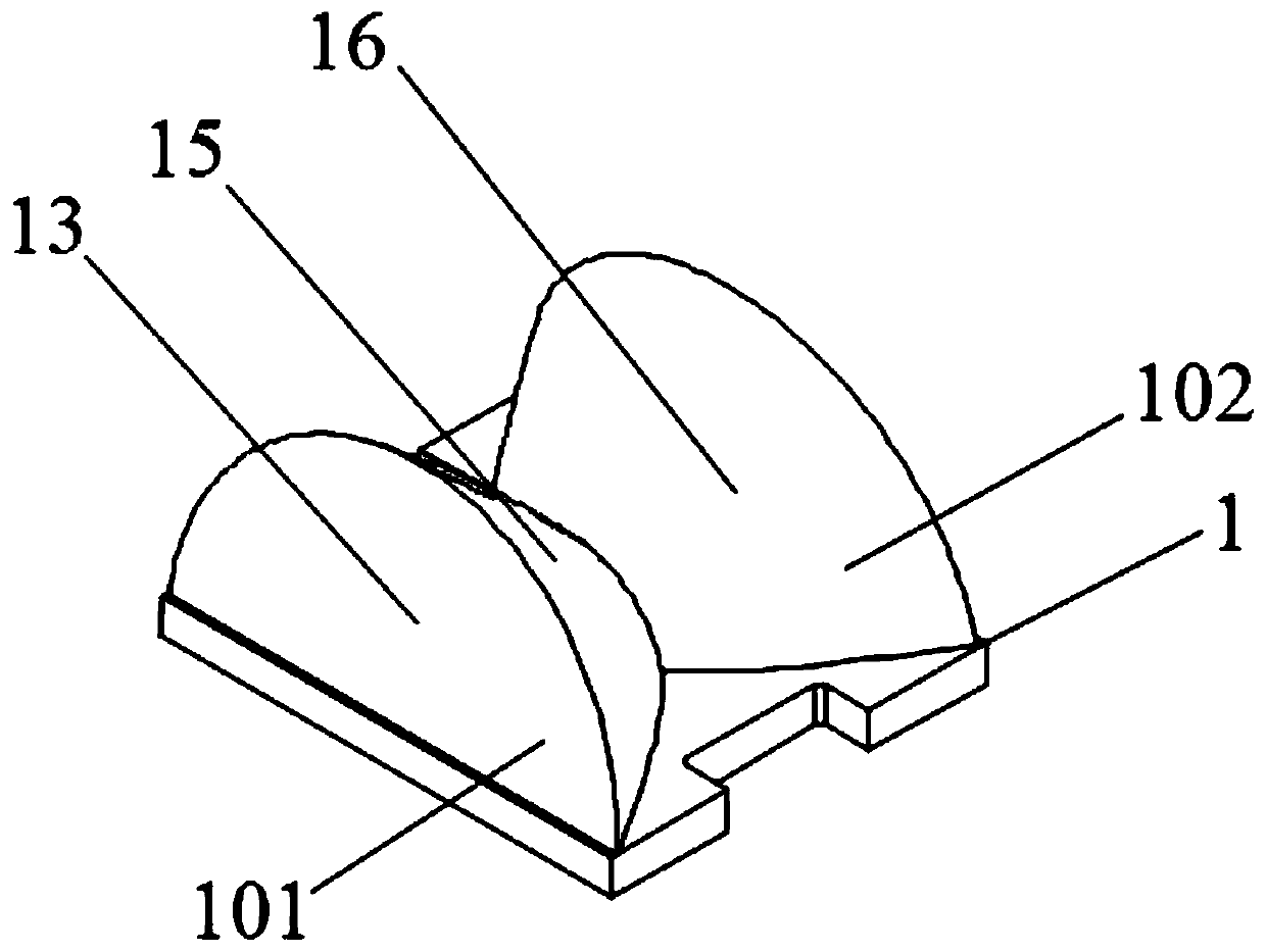
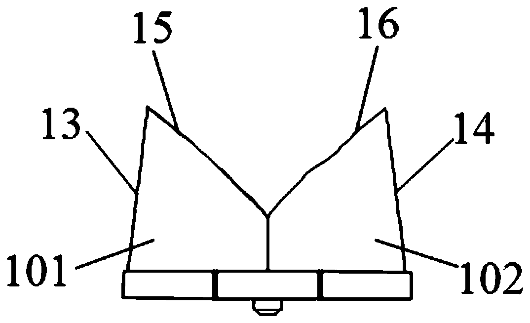
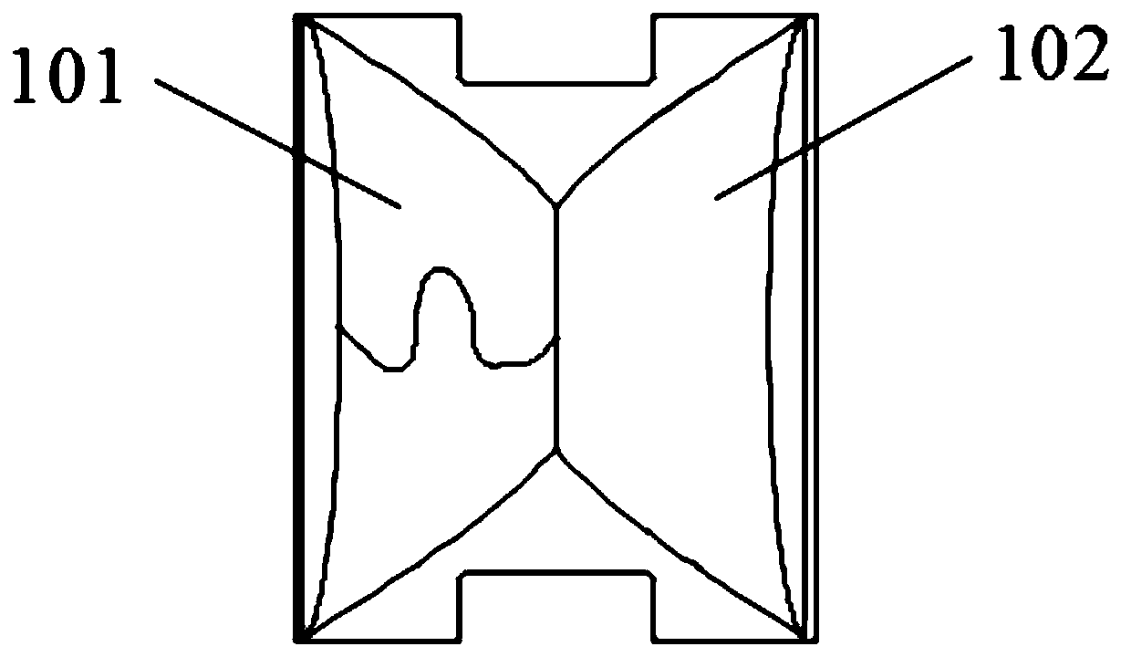
[0024] Such as figure 1 , 2 As shown, this embodiment provides a LED polarized lens 1 with uniform luminosity, which is arranged above the PCB circuit board. The LED polarized lens 1 is provided with a lens cavity top surface 10, a first lens cavity side surface 11, a second lens cavity Side 12, the first lens reflection surface 13, the second lens reflection surface 14 and the first lens exit surface 15 and the second lens exit surface 16, the first lens exit surface 13, the first lens reflection surface 15, the second lens reflection surface 16 and the second lens exit surface 14, the cross-sectional outline of the lens body is M-shaped.

[0025] In this example, if image 3 As shown, the len...


PUM


Abstract

The invention provides an LED polarized lens with uniform brightness. The LED polarized lens is arranged above a PCB circuit board, the LED polarized lens is provided with a lens inner cavity top surface, a first lens inner cavity side, a second lens inner cavity side, a first lens reflecting surface, a second lens reflecting surface, a first lens exit surface and a second lens exit surface, wherein the cross-sectional contour of a lens main body formed by the first lens exit surface, the first lens reflecting surface, the second lens reflecting surface and the second lens exit surface is M-shaped, and the lens main body is composed of a first lens assembly and a second lens assembly which are symmetrical at left and right. According to the invention, the LED polarized lens can project thelight emitted from the LED light source to the area of 70-80 degrees, and the width and height of a receiving area are the relationship of about five times, a small angle of focusing is realized, theratio of a maximum light intensity to lumen reaches 2Cd / Lm, the light spot effect in an LED light receiving area has a uniform transition, the illuminance uniformity reaches 1:1 .1, so that the illuminance uniformity of an LED lamp is improved, and a lamp power is reduced under the same illuminance.

Description

technical field [0001] The invention relates to the technical field of LED lenses and LED lighting, in particular to an LED polarized lens with uniform luminosity. Background technique [0002] The combination of LED lens and LED light source can enhance the use efficiency and luminous efficiency of light, and form an optical system that uses different lenses to change the light field distribution of the LED light source. The LED light source without light distribution is an approximate Lambertian body. The Lambertian body means that when the incident energy is uniformly reflected in all directions, that is, the incident energy is centered on the incident point and isotropically reflected around the entire hemispherical space. The phenomenon of energy is called diffuse reflection, also known as isotropic reflection, and a complete diffuser is called a Lambertian body. The corresponding receiving surface of the approximate Lambertian body formed by the LED light source witho...

Claims


Application Information

Patent Timeline
Patent Type & Authority Applications(China)
IPC IPC(8): F21V5/04F21V23/00F21V19/00F21Y115/10
CPCF21V5/04F21V19/001F21V23/003F21Y2115/10
Inventor 戴柳叶王会春陈伟李春荣
Owner HUIZHOU LIGHT ENGINE LTD
Learn More