
Optical fiber illumination apparatus

a technology of optical fiber and illumination apparatus, which is applied in the direction of lighting and heating apparatus, instruments, fibre light guides, etc., can solve the problems of optical fibers not being positioned in place, the commodity of optical fiber lamps degrades, and the optical fibers may be easily displaced

Active Publication Date: 2022-09-13
HYUNDAI MOTOR CO LTD +1
View PDF18 Cites 0 Cited by
  • Summary
  • Abstract
  • Description
  • Claims
  • Application Information

AI Technical Summary

Benefits of technology

[0008]Various aspects of the present invention are directed to providing an optical fiber illumination apparatus having high light efficiency and uniform luminosity and being configured for displaying various illumination patterns with optical fibers.
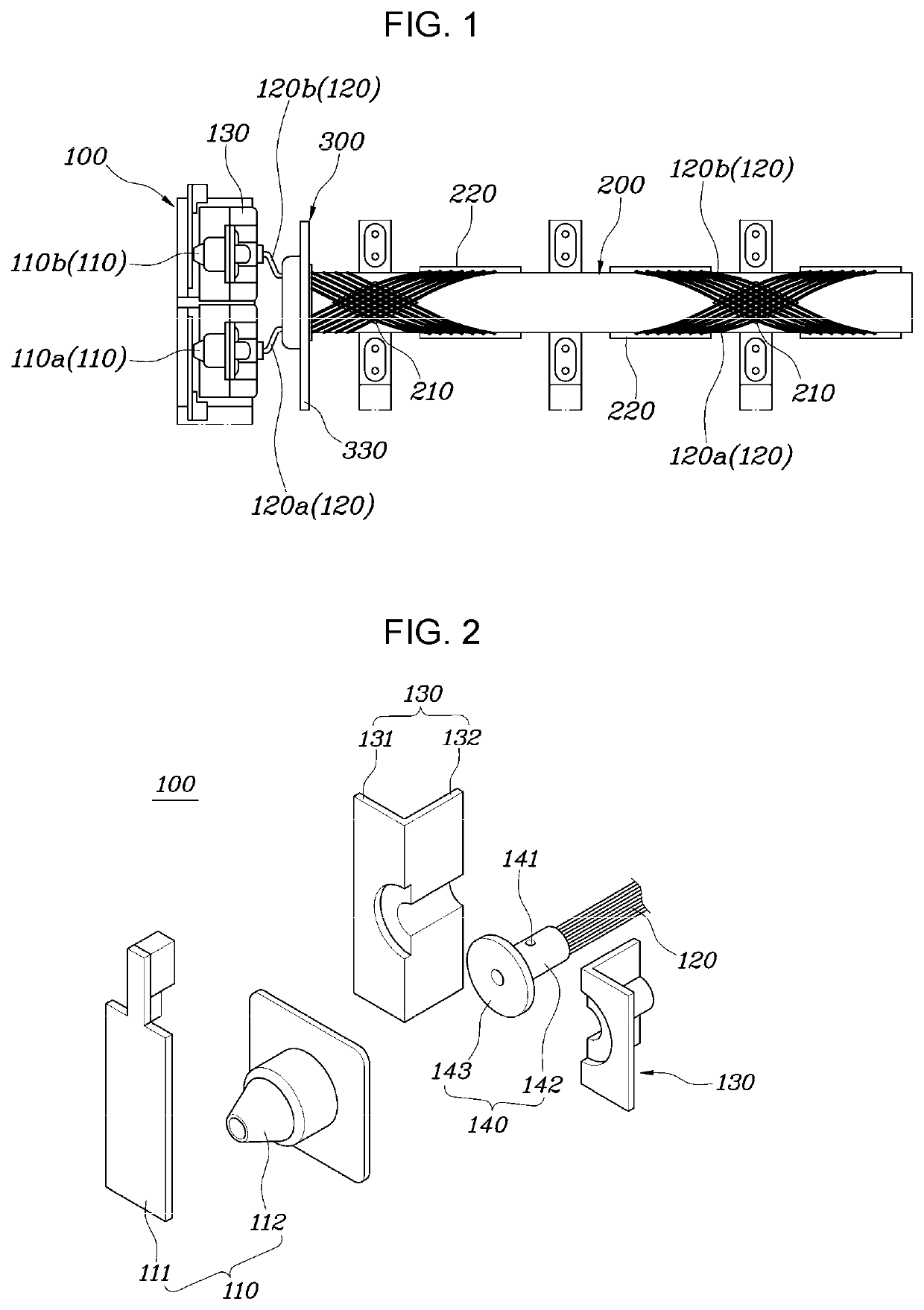
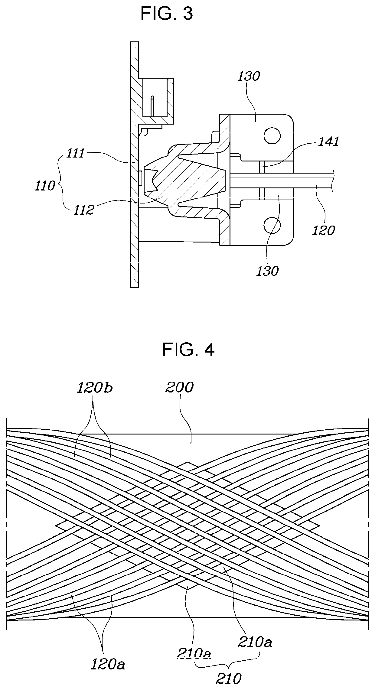
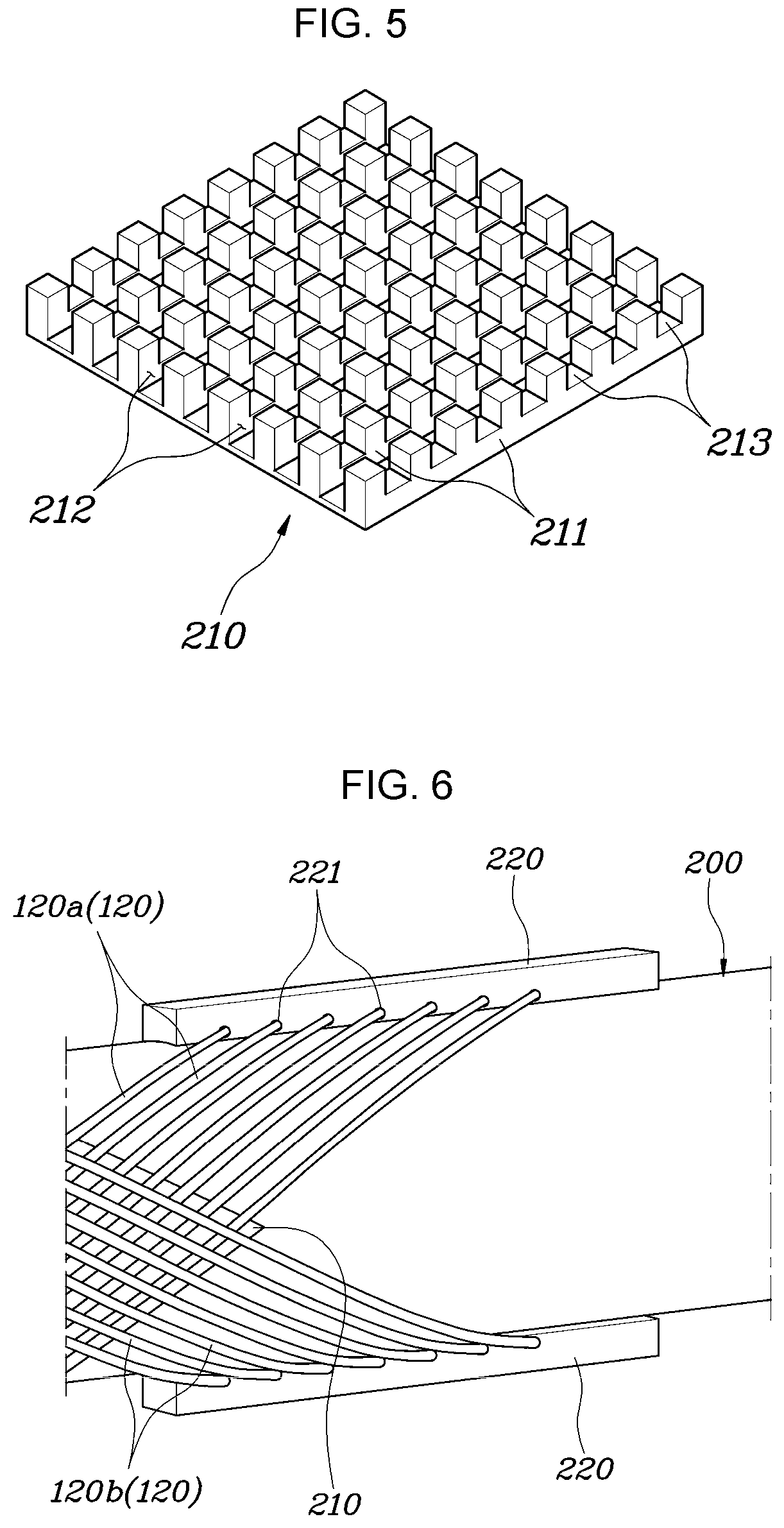
[0009]According to various aspects of the present invention, there is provided an optical fiber illumination apparatus including a light source module, a guide unit, and a fixing unit. The light source module includes a light source configured to emit light and a group of optical fibers, each being configured to transmit the light introduced thereinto from the light source. The guide unit longitudinally extends and is configured to fix arrangement and positions of the optical fibers arranged on an external surface thereof, facilitating an illumination pattern to be displayed by the optical fibers. The fixing unit is disposed between the light source module and the guide unit and makes the optical fibers arranged at predetermined intervals in a circumferential direction of the guide unit.
[0024]The fixing unit may include a light shielding film disposed on the cover portion and configured to prevent light leaking from a portion of the optical fiber between the light source module and the fixing unit from entering the guide unit.
[0029]The optical fiber illumination apparatus structured as described above ensures high light efficiency and luminosity uniformity when lighting with optical fibers and can display various illumination patterns using flexible optical fibers.

Problems solved by technology

In that case, the commodity of optical fiber lamps degrades due to the luminosity irregularity.
Furthermore, since optical fibers are not rigid but flexible, the optical fibers may not be positioned in place and may be easily displaced when impacted.

Method used


Image

  • Optical fiber illumination apparatus
  • Optical fiber illumination apparatus
  • Optical fiber illumination apparatus

Examples


Embodiment Construction

[0041]Reference will now be made in detail to various embodiments of the present invention(s), examples of which are illustrated in the accompanying drawings and described below. While the present invention(s) will be described in conjunction with exemplary embodiments of the present invention, it will be understood that the present description is not intended to limit the present invention(s) to those exemplary embodiments. On the other hand, the present invention(s) is / are intended to cover not only the exemplary embodiments of the present invention, but also various alternatives, modifications, equivalents and other embodiments, which may be included within the spirit and scope of the present invention as defined by the appended claims.

[0042]Hereinbelow, an optical fiber illumination apparatus according to exemplary embodiments of the present invention will be described with reference to the accompanying drawings.

[0043]FIG. 1 is a diagram illustrating an optical fiber illuminatio...


PUM

PropertyMeasurementUnit
diameteraaaaaaaaaa
lengthaaaaaaaaaa
lengthsaaaaaaaaaa

Abstract

Disclosed is an optical fiber illumination apparatus configured for ensuring high light efficiency and uniform luminosity when displaying an illumination pattern with flexible optical fibers in fiber optic lighting.

Description

CROSS REFERENCE TO RELATED APPLICATION[0001]The present application claims priority to Korean Patent Application No. 10-2020-0090483, filed Jul. 21, 2020, the entire contents of which is incorporated herein for all purposes by this reference.BACKGROUND OF THE INVENTIONField of the Invention[0002]The present invention relates to an optical fiber illumination apparatus capable of ensuring high light efficiency and uniform luminosity when displaying an illumination pattern with flexible optical fibers in fiber optic lighting.Description of Related Art[0003]Vehicles are provided with lamp apparatuses that help a driver secure good forward visibility when driving at night and for informing other vehicle drivers or nearby pedestrians of the driving conditions thereof.[0004]The primary role of the lamp apparatuses is lighting, but the lamp apparatuses also function as components affecting aesthetic impression of vehicles. That is, since impression of a vehicle can change according to an il...

Claims


Application Information

Patent Timeline
Patent Type & Authority Patents(United States)
IPC IPC(8): F21V8/00G02B6/42F21S43/237G02B6/38
CPCG02B6/001F21S43/237G02B6/0006G02B6/4257F21V2200/10G02B6/3861F21S41/24F21S41/29F21S41/19F21S41/40F21S41/47F21S41/32F21W2102/20F21W2107/10F21S43/245F21S43/27F21S43/26F21S43/14G02B6/0008G02B6/4206G02B6/04F21S43/236F21W2102/10F21W2103/00
Inventor AHN, BYOUNG SUKLEE, KI HONGLIM, JUNG WOOKHAN, SEUNG SIKKIM, JI YEONYU, JIN HEE
Owner HYUNDAI MOTOR CO LTD
Learn More