Auto-reverse tape deck comprising switching device

A technology of conversion device and tape transport mechanism, which is applied in the direction of speed change/reversal device, record carrier drive mechanism, manual/electromagnetic control, etc.

Inactive Publication Date: 2003-07-02
KONINKLIJKE PHILIPS ELECTRONICS NV
View PDF5 Cites 0 Cited by
  • Summary
  • Abstract
  • Description
  • Claims
  • Application Information

AI Technical Summary

Problems solved by technology

The disadvantage of this known construction is also that two separate drive ca

Method used


Image

  • Auto-reverse tape deck comprising switching device
  • Auto-reverse tape deck comprising switching device
  • Auto-reverse tape deck comprising switching device

Examples


Embodiment Construction

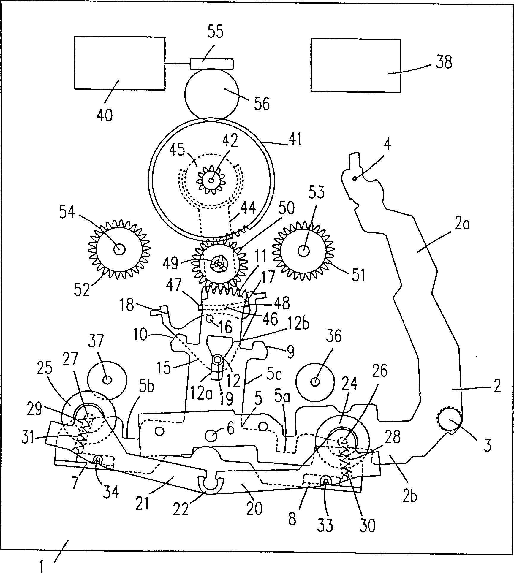
[0039] figure 1 , 2, 3, 4 and 5 diagrammatically represent the components of the automatic rewind mechanism in plan view in different operating states. figure 1 Indicates the operating position of the first tape transport direction (fast reverse playback), such as figure 1 As shown, the belt transport mechanism of the present invention includes a bottom plate made of a deck 1, on which a bearing part 2 is fixed so as to rotate around a pivot 3, the bearing part 2 has an arm 2a and an arm 2b, and the arm 2a of the bearing part 2 With guide pin 4. The guide pin 2c engages with an unillustrated cam surface of an unillustrated cam disc. A cam disc, not shown, applies to the guide pin 2c the force required to turn the carrier part 2 about the pivot 3 . A head tape guide member not shown is supported on the carrier member 2 . A tape guide member, not shown, moves towards the tape in the cassette by rotating the carrying member 2 about the pivot 3, not shown. The drive rod 5 ...


PUM


Abstract

The present invention provides a apparatus comprising an actuating lever 5, which is mounted on a carrier element 2 in a freely rotatable/movable manner, is connected to first and second pressing roller levers 20 and 21. The setting of the lever 5 is changed from one operating position to another at the time of the change in the tape transporting direction. At the time of the change in the tape transporting direction, the levers 20 and 21 are moved to one operating position to another by the lever 5 and the positions of two levers 20 and 21 are decided by the position of the lever 5 in the first and the second tape transporting directions.

Description

technical field [0001] The invention relates to a switching device used in an automatic rewinding mechanism of a cassette tape machine, wherein the first pressure roller fixed on the first pressure roller control rod is used in the first tape conveying direction, and the first pressing roller of the switching device The working position acts on the first drive wheel for the second tape transport direction, and the second pressure roller fixed on the second pressure roller control lever acts on the second drive wheel at the second working position of the conversion device, wherein The magnetic head is arranged on the bearing part fixed on the platform, and moves at different positions relative to the conveying path of the magnetic tape. Background technique [0002] European patent EP367371A2 discloses such a switching device, the known device comprising a carrier supported on a deck for movement in a direction perpendicular to the tape transport path. The diverter plate is ...

Claims


Application Information

Patent Timeline
IPC IPC(8): G11B15/10G11B15/02G11B15/28G11B15/29G11B15/44
CPCG11B15/29G11B15/442G11B15/02
Inventor N·孔策S·科哈
Owner KONINKLIJKE PHILIPS ELECTRONICS NV
Why Eureka
Try Eureka