
Screening device for wear-resisting ball machining

A screening device, wear-resistant ball technology, applied in the direction of filter screen, solid separation, grille, etc., can solve the problems of inability to adapt to multi-size wear-resistant ball screening, affecting production efficiency and production cost, requiring manual cleaning, etc. The effect of self-cleaning ability, improving production efficiency and reducing production cost

Inactive Publication Date: 2020-06-26
合肥新士鑫机械科技有限公司
View PDF0 Cites 0 Cited by
  • Summary
  • Abstract
  • Description
  • Claims
  • Application Information

AI Technical Summary

Problems solved by technology

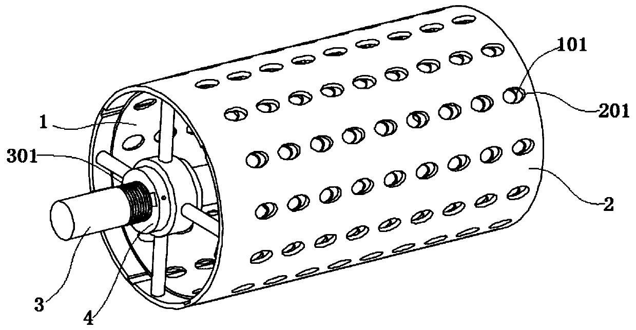
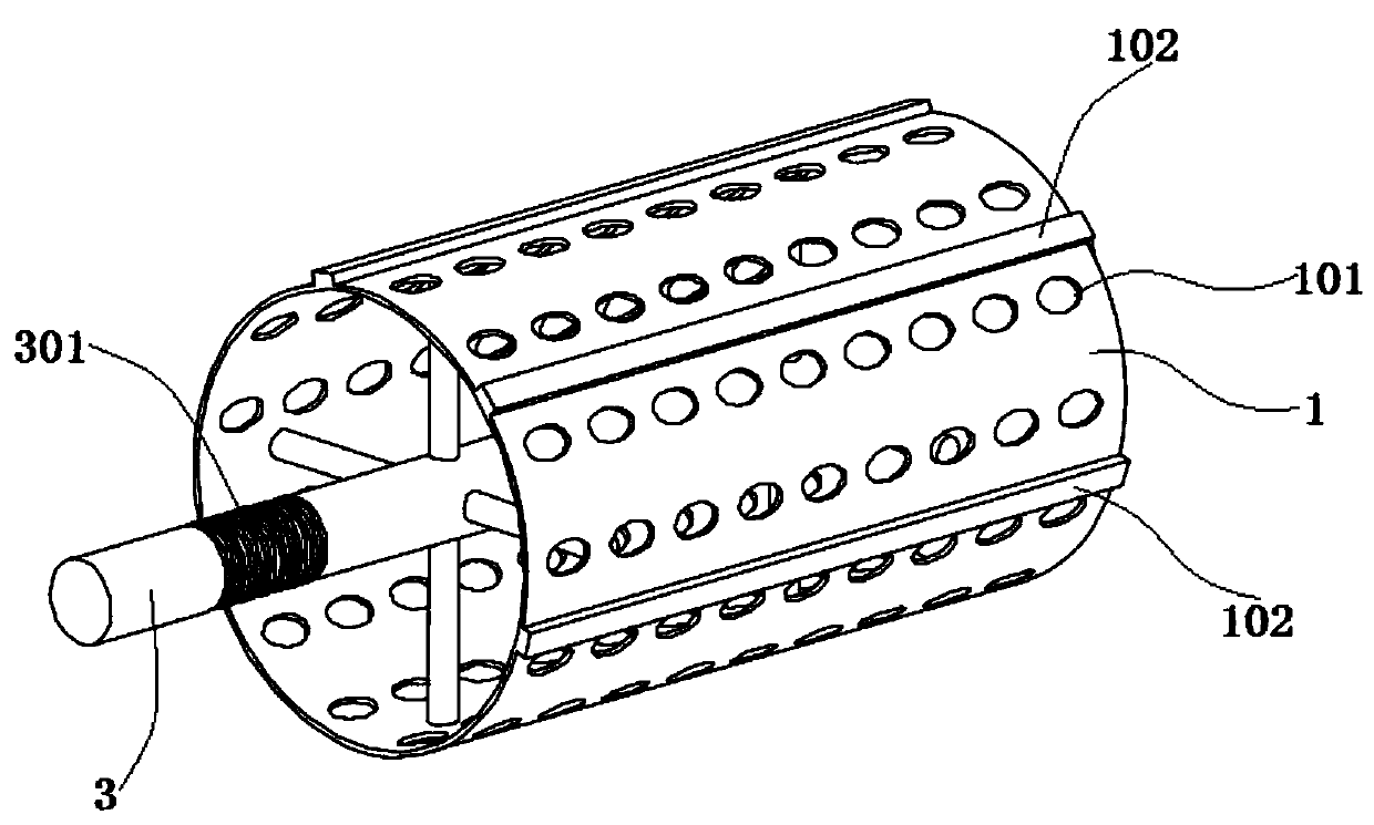
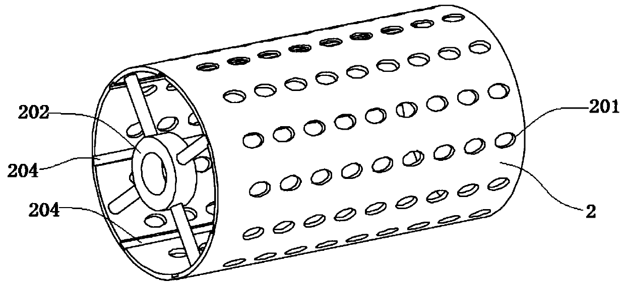
[0004] The object of the present invention is to provide a screening device for wear-resistant ball processing, by setting the inner rolling screen and the outer rolling screen that can slide and cooperate with each other; using the mutual displacement between the first screen hole and the second screen hole to change the mesh The size solves the problem that the screening equipment cannot adapt to the screening of multi-size wear-resistant balls and has poor adaptability; at the same time, through the mutual misalignment adjustment between the first screen hole and the second screen hole, the wear-resistant ball stuck in the screen hole can be effectively removed , to solve the need for manual cleaning, affecting production efficiency and production costs

Method used


Image

  • Screening device for wear-resisting ball machining
  • Screening device for wear-resisting ball machining
  • Screening device for wear-resisting ball machining

Examples


Embodiment Construction

[0030] The following will clearly and completely describe the technical solutions in the embodiments of the present invention with reference to the accompanying drawings in the embodiments of the present invention. Obviously, the described embodiments are only some, not all, embodiments of the present invention. Based on the embodiments of the present invention, all other embodiments obtained by persons of ordinary skill in the art without creative efforts fall within the protection scope of the present invention.

[0031] In describing the present invention, it should be understood that the terms "opening", "upper", "lower", "one end", "top", "side", "length", "inner", "surrounding" etc. Indicating orientation or positional relationship is only for the convenience of describing the present invention and simplifying the description, and does not indicate or imply that the components or elements referred to must have a specific orientation, be constructed and operated in a speci...


PUM


Abstract

The invention discloses a screening device for wear-resisting ball machining, and relates to the technical field of wear-resisting ball production. The screening device for wear-resisting ball machining comprises an inner roller screen and an outer roller screen; the inner surface of the inner roller screen is fixedly connected with a transmission shaft through a connecting rod; first screen holesare arrayed in the peripheral side surface of the inner roller screen; external threads are arranged on the peripheral side of the transmission shaft; the inner surfaces of the two ends of the outerroller screen are fixedly connected with a first connecting sleeve and a second connecting sleeve through connecting rods correspondingly; and the first connecting sleeve is connected with the transmission shaft through an adjusting sleeve. According to the screening device for wear-resisting ball machining, the inner roller screen and the outer roller screen which can be in sliding fit with eachother are arranged, and the size of a screen mesh is changed through utilizing mutual dislocation between the first screen holes and second screen holes, so that the problems that screen equipment cannot adapt to screening of multi-size wear-resisting balls and consequently is poor in adaptability are solved; and meanwhile, through mutual dislocation adjustment between the first screen holes and the second screen holes, the wear-resisting balls clamped in the screen holes can be effectively removed, and the problems that the production efficiency and the production cost are influenced due to the fact that manual cleaning is needed can be solved.

Description

technical field [0001] The invention belongs to the technical field of wear-resistant ball production, in particular to a screening device for wear-resistant ball processing. Background technique [0002] Wear-resistant ball is a kind of crushing medium used in ball mills, which is used to crush the materials in the mill. Different ball mills and different industries have different requirements for the size of wear-resistant balls. Therefore, wear-resistant balls need to be screened and classified according to size after processing. [0003] The wear-resistant ball sorting and testing equipment in the prior art can only screen out wear-resistant balls of a certain size in one screening, and the adaptability is poor. However, when there are wear-resistant balls of various sizes in the wear-resistant balls to be screened, multiple screenings and screening equipment of different sizes are required to thoroughly screen wear-resistant balls of different sizes, resulting in low s...

Claims


Application Information

Patent Timeline
IPC IPC(8): B07B1/24B07B1/42B07B1/46
CPCB07B1/24B07B1/4609B07B1/4636
Inventor 叶雷
Owner 合肥新士鑫机械科技有限公司
Learn More