
Display signal synchronization method and conversion device

A display signal and synchronous conversion technology, which is applied in image communication, TV, color TV parts, etc., can solve the problem that the input and output signals cannot be synchronized

Active Publication Date: 2020-06-23
珠海亿智电子科技有限公司
View PDF7 Cites 5 Cited by
  • Summary
  • Abstract
  • Description
  • Claims
  • Application Information

AI Technical Summary

Problems solved by technology

[0005] In order to solve the problem that the input and output signals cannot be synchronized, the embodiment of the present invention provides a display signal synchronization method and conversion device

Method used


Image

  • Display signal synchronization method and conversion device
  • Display signal synchronization method and conversion device
  • Display signal synchronization method and conversion device

Examples


Embodiment 1

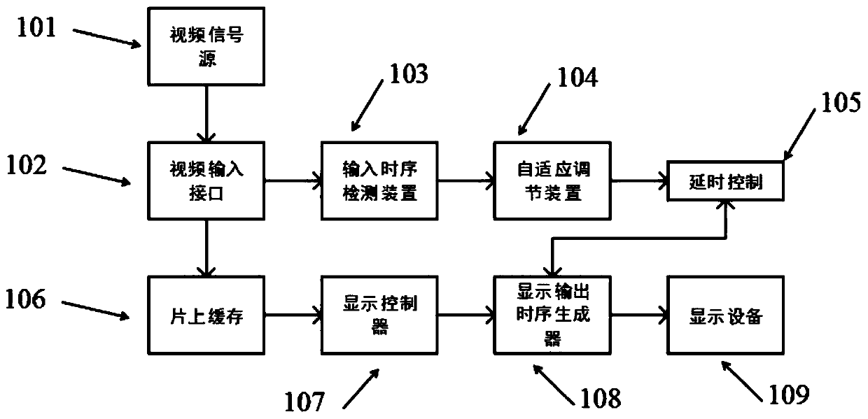
[0042] refer to figure 1 As shown, the display signal synchronous conversion device provided in this embodiment includes a video input interface 102, an input timing detection module 103, an adaptive adjustment module 104, a delay control module 105, an on-chip cache 106, a display controller 107, and a display output timing generation device 108. In this embodiment, the application scenario of the device is that the external video signal source does not have the function of inputting an external frame synchronization signal.

[0043]Wherein, the video input interface 102 is used for receiving the input video signal transmitted by the external video signal source 101; the input timing detection module 103 is used for detecting the timing parameter of the input video signal, and judging whether the timing of the input video signal is The device supports synchronous operation; at the same time, by setting the input timing detection module 103 and measuring the timing parameters...

Embodiment 2

[0063] refer to Figure 4 As shown, the components of the display signal synchronous conversion device provided in this embodiment are basically the same as in Embodiment 1, the difference is that the application scenario of the display signal synchronous conversion device provided in this embodiment is that the external video signal source has an input case of the external frame sync signal function.

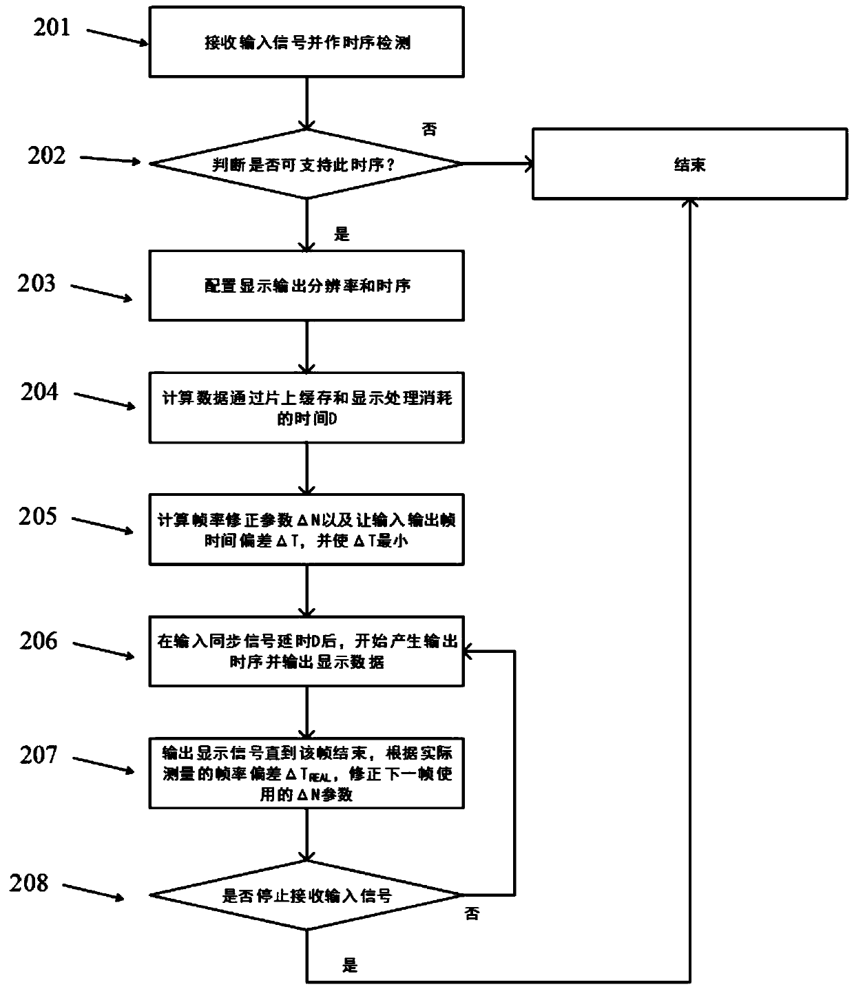
[0064] In this application scenario, the display signal synchronization method provided by this embodiment also firstly detects the timing parameter of the video input signal by the input timing detection module, and judges whether the timing parameter of the input video signal is the timing parameter of the display device. The synchronous operation of this method can be carried out; if the input video signal can carry out the synchronous operation of this method, the delay control module then outputs a trigger signal with a controllable delay time to the external video signal ...


PUM


Abstract

The invention discloses a display signal synchronization method and a conversion device. The method comprises the steps that a video access interface receives an input video signal transmitted by a video signal source, and an input time sequence detection module detects a time sequence parameter of the video input signal to judge whether the time sequence parameter of the input video signal is a time sequence parameter of display equipment or not and judge whether synchronous operation of the method can be carried out or not; on the occasion that an external video signal source outputs a self-contained frame synchronization signal and data; and the time delay control module outputs a trigger signal with controllable time delay to the display output time sequence generator, and the displayframe synchronization signal output by the display output time sequence generator has controllable time delay relative to the frame synchronization signal of the video source, so that the output videosignal is output to the display equipment for display according to the output time sequence. Compared with the traditional technology in which a DRAM (Dynamic Random Access Memory) and other memoriesare needed to cache video data, the method only needs very small on-chip cache, and only brings time delay of on-chip cache and display processing.

Description

technical field [0001] The invention relates to video signal processing technology, in particular to a display signal synchronization method and conversion device. Background technique [0002] When receiving a real-time video signal and displaying it on a display device, there is usually a deviation in the data synchronization clock frequency used between the input device and the output device. Even signals of the same video standard may have a very small deviation, such as 148.5 MHz and 148.501MHz, resulting in a very small deviation between the input and output frame rates, such as 60Hz and 60.0004Hz. The traditional method is to first receive a complete frame of video signal through a large-capacity medium such as DRAM in the system, and then output the video signal to the display device asynchronously through the frequency of the local clock, which inevitably requires DRAM space and Bandwidth, for software process control, even multiple buffer polls are needed to solve...

Claims


Application Information

Patent Timeline
Patent Type & Authority Applications(China)
IPC IPC(8): H04N5/067H04N5/765
CPCH04N5/067H04N5/765
Inventor 不公告发明人
Owner 珠海亿智电子科技有限公司
Learn More