A kind of preparation method of focusing metasurface reflectarray antenna

A reflective array antenna and reflective array technology, which is applied in the direction of manufacturing antenna array devices, antennas, antenna arrays, etc., can solve the problems of low utilization rate of phase shift units, inability to achieve long-distance high-efficiency energy transmission, etc. Area utilization, easy disassembly and transport, overcoming the effect of complex feeding

Active Publication Date: 2022-02-01
XI AN JIAOTONG UNIV
View PDF4 Cites 0 Cited by
  • Summary
  • Abstract
  • Description
  • Claims
  • Application Information

AI Technical Summary

Problems solved by technology

The shortcomings of this method are: 1. The metal patch on the dielectric plate is a trioscillator. When the metal patch covers the dielectric plate, the utilization rate per unit area of ​​the phase shift unit is not high.
2. The antenna designed by this method cannot achieve long-distance high-efficiency energy transmission due to the size and focus setting

Method used


Image

  • A kind of preparation method of focusing metasurface reflectarray antenna
  • A kind of preparation method of focusing metasurface reflectarray antenna
  • A kind of preparation method of focusing metasurface reflectarray antenna

Examples


preparation example Construction

[0051] A method for preparing a focusing metasurface reflectarray antenna, comprising the following steps:

[0052] Step 1, determining the phase shift unit structure of the metasurface reflective array;

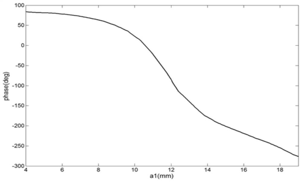
[0053] Step 2, draw the phase shift curve, use the Floquet port in HFSS to simulate the length of the ring patch of the phase shift unit within the value range in turn, and obtain the corresponding reflection phase under different lengths, and draw the patch length and reflection phase as a line phase shift curve;

[0054] Step 3, determining the size of the focusing metasurface array, the metasurface array is composed of N*N phase shifting units;

[0055] Step 4. Determine the feed horn and its position. The center operating frequency of the horn is 5.8GHz and the height is H. Determine the focal diameter ratio H / L according to the feed source pattern, and optimize the optimal focal diameter ratio as H / L=0.64.

[0056] Step 5, determine the focusing position of the metasu...

Embodiment

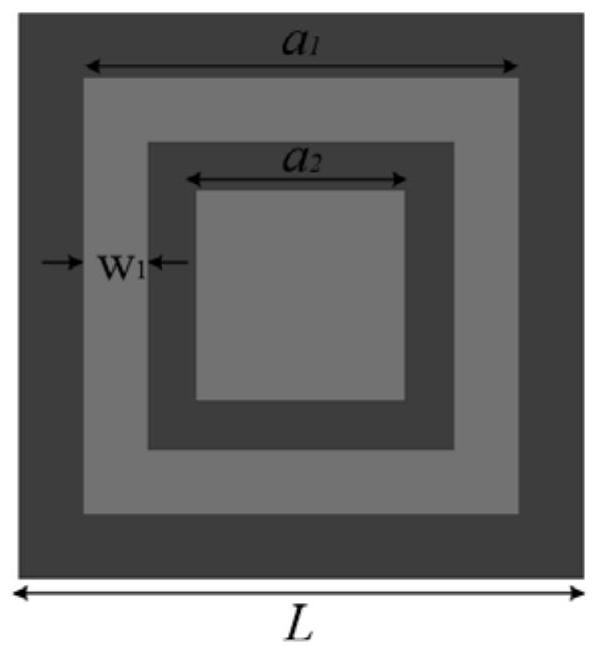
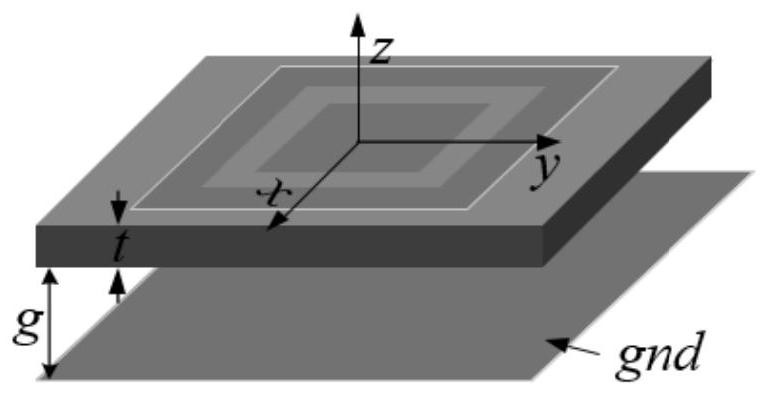
[0069] Step 1 Determine the phase shift unit structure of the metasurface reflective array, such as figure 1 . The unit patch consists of a square and a concentric square ring. The ratio of the length of the square patch to the length of the circular patch is s, and the ratio of the width of the circular patch to the length is q.

[0070] Ring patch length a 1 The value range is 4mm1 <=19mm, the ratio of the length of the square patch to the length of the ring patch is s is 0.65, and the ratio of the width of the ring patch to the length is q is 0.01. In order to avoid grating lobes, the unit spacing d is less than λ / 2, which is 19mm. In order to make the phase shift curve smoother, the thickness g of the air layer is 5.5mm. The thickness t of the dielectric substrate is 0.75 mm.

[0071] Step 2 Draw the phase shift curve. Use the Floquet port in HFSS to convert the ring patch length of the phase shift unit to a 1 The simulation is carried out sequentially within the ra...


PUM


Abstract

The invention discloses a focusing metasurface reflective array antenna and a preparation method thereof. The reflective array antenna is composed of a feed horn and 3600 phase shift units, does not require a complicated feed network, has simple manufacturing process, and low processing cost. Flat surface for easy disassembly and transport. The unit patch is composed of a square and a concentric square ring, the phase shift compensation range is large, and the phase shift is not sensitive to processing errors. At the same time, the area utilization rate of the phase shift unit is high, the reflection characteristics are good, and the loss is low; multi-point focusing is adopted on the axis, so that the antenna maintains a high transmission efficiency over a long distance. Finally, the energy transmission efficiency in the range of 10m can reach more than 45%, which is suitable for popularization and application in the field of microwave wireless energy transmission.

Description

technical field [0001] The invention belongs to the field of wireless energy transmission, in particular to a focusing metasurface reflective array antenna and a preparation method thereof. Background technique [0002] With the development of science and technology and the progress of the times, the traditional wired power transmission method can no longer meet people's living needs. Therefore, the realization of wireless power transfer (WPT) will make the human application of electric energy wider and more flexible. According to different transmission mechanisms, in order to achieve long-distance transmission, microwave wireless power transmission can be used for far-field radiation, but this system suffers from far-field distance loss due to the divergence of the transmitted beam. With near-field focusing (NFF), theoretically speaking, the electromagnetic waves from the transmitting source can be converged at a certain point in the near-field region of the antenna radiat...

Claims


Application Information

Patent Timeline
Patent Type & Authority Patents(China)
IPC IPC(8): H01Q1/36H01Q1/38H01Q13/02H01Q15/14H01Q21/00
CPCH01Q1/36H01Q1/38H01Q13/02H01Q21/0006H01Q21/0087H01Q15/14
Inventor 文瑶保荣刘纯亮
Owner XI AN JIAOTONG UNIV
Why Eureka
Try Eureka