
Clamp suitable for impedance measurement under high-temperature and high-frequency conditions

An impedance measurement, high-frequency technology, applied in the field of impedance measurement fixtures under high temperature and high frequency conditions, can solve the problems of difficult to meet the measurement temperature requirements, difficult to meet the measurement requirements, limited measurement temperature, etc., to improve convenience and durability. High temperature characteristics, the effect of improving measurement accuracy

Inactive Publication Date: 2020-06-23
GUANGXI UNIVERSITY OF TECHNOLOGY
View PDF4 Cites 0 Cited by
  • Summary
  • Abstract
  • Description
  • Claims
  • Application Information

AI Technical Summary

Problems solved by technology

[0002] The existing high-temperature and high-frequency impedance measurement systems usually have the following defects: 1. The measurement frequency is limited, and the measurement frequency is limited to below 20MHz, which makes it difficult to meet the measurement requirements under specific conditions, and it is difficult to achieve real measurement under high-frequency conditions; 2. , The measurement temperature is limited. Due to the limitation of the fixture material, the thermal deformation of the fixture exceeds the required range under high temperature conditions, which affects the measurement results and is difficult to meet the specific measurement temperature requirements.

Method used


Image

  • Clamp suitable for impedance measurement under high-temperature and high-frequency conditions

Examples


Embodiment 1

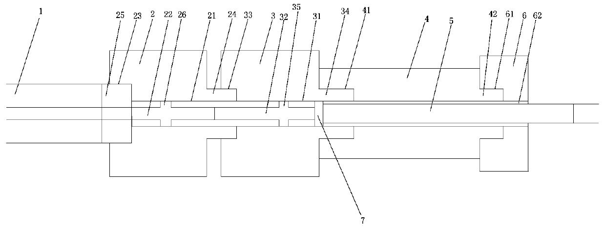
[0030] Such as figure 1 As shown, the fixture provided in this embodiment is suitable for impedance measurement under high temperature and high frequency conditions, including data line 1, connector I2, connector II3, outer tube 4, and inner column 5;

[0031] The joint I2 is provided with a through hole I21 extending in the left and right directions, and a guide post I22 is fixed in the through hole I21, and the guide post I22 is arranged in the axial direction of the through hole I21; the data line 1. The left end is connected to the vector network analyzer, and the right end is inserted into the joint I2 to connect with the guide post I22; the left end of the joint II3 is matched with the right end of the joint I2 and can be connected into one; the joint II3 is set in the left and right directions The through hole II31, the guide post II32 is fixed inside the through hole II31, the guide post II32 is arranged along the axial direction of the through hole II31, and the right...


PUM


Abstract

The invention aims to provide a clamp suitable for impedance measurement under high-temperature and high-frequency conditions. The clamp comprises a data line, a joint I, a joint II, an outer pipe andan inner column, the connector I is provided with a through hole I formed in the left-right direction, a guide column I is fixedly arranged in the through hole I, and the guide column I is arranged in the axial direction of the through hole I; the left end of the data line is connected with the vector network analyzer, and the right end extends into the joint I to be connected with the guide pillar I; the left end of the joint II and the right end of the joint I are matched and can be connected into a whole; the connector II is provided with a through hole II formed in the left-right direction, a guide column II is fixedly arranged in the through hole II and arranged in the axial direction of the through hole II, the right end of the guide column II is located in the through hole II, anda distance is reserved between the right end of the guide column II and a right end opening of the through hole II; the left end of the outer pipe and the right end of the joint II are matched and canbe connected into a whole; the inner column is arranged in the outer pipe and extends in the axial direction of the outer pipe. The clamp overcomes the defects in the prior art, and has the characteristics of reasonable structure, wide application range and high measurement precision.

Description

technical field [0001] The invention relates to the field of auxiliary devices for material impedance testing, in particular to a fixture suitable for impedance measurement under high temperature and high frequency conditions. Background technique [0002] The existing high-temperature and high-frequency impedance measurement systems usually have the following defects: 1. The measurement frequency is limited, and the measurement frequency is limited to below 20MHz, which makes it difficult to meet the measurement requirements under specific conditions, and it is difficult to achieve real measurement under high-frequency conditions; 2. 1. The measurement temperature is limited. Due to the limitation of the fixture material, the thermal deformation of the fixture exceeds the required range under high temperature conditions, which affects the measurement results and makes it difficult to meet the specific measurement temperature requirements. Contents of the invention [0003...

Claims


Application Information

Patent Timeline
Patent Type & Authority Applications(China)
IPC IPC(8): G01R27/02G01R1/04
CPCG01R1/0425G01R27/02
Inventor 梁程华张宇豪罗嫄
Owner GUANGXI UNIVERSITY OF TECHNOLOGY
Learn More