
Simulation device for three-dimensional solute transport in porous medium and experimental method

A technology of porous media and solute transport, applied in the field of soil physics research, can solve the problems of increasing the economic pressure of observation wells, influence of experimental results, observation errors, etc., and achieve the effects of automatic data observation, convenient experimental methods and high reliability.

Active Publication Date: 2020-06-23
JILIN UNIV
View PDF6 Cites 3 Cited by
  • Summary
  • Abstract
  • Description
  • Claims
  • Application Information

AI Technical Summary

Problems solved by technology

However, regardless of the horizontal soil column method or the vertical soil column method, due to the limitation of the side wall of the column, the water flow can only be forced to move nearly one-dimensionally, while in nature, due to the heterogeneity of the porous medium itself, the water flow The movement is often three-dimensional, and the difference in the form of this movement will have a greater impact on the experimental results, thereby causing observation errors
The field tracer test method maintains the movement shape of the water flow well, but the observation of the pollutant dispersion plume often requires a large number of observation wells. Too few observation wells will affect the observation accuracy, but increasing the number of observation wells will not would cause enormous economic pressure

Method used


Image

  • Simulation device for three-dimensional solute transport in porous medium and experimental method
  • Simulation device for three-dimensional solute transport in porous medium and experimental method
  • Simulation device for three-dimensional solute transport in porous medium and experimental method

Examples


Embodiment Construction

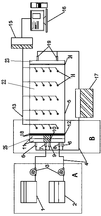
[0034] like Figure 1 to Figure 4 As shown, a three-dimensional solute migration simulation device in porous media includes a sand tank 5, an injection mode adjustment device B, a liquid supply device A, a permeate collection device 17, a water barrier 12, a well pipe 14, and a conductivity electrode 21. Data collector 15 and data processing system 16:

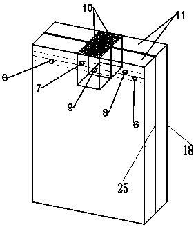
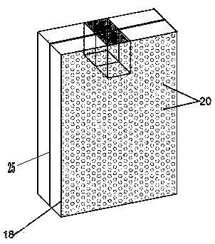
[0035] The liquid supply device A includes a tracer liquid supply tank 1, a distilled water supply tank 2 and a peristaltic pump 3; the sand tank left chamber 11 of the sand tank 5, the suspended sub-chamber 10, the water baffle 12, the first baffle 18 and The third baffle plate 25 densely covered with permeable holes constitutes the injection mode adjusting device B;

[0036] The sand tank 5 is placed horizontally, and the inside of the sand tank 5 is divided into a sand tank left chamber 11, a middle sub-chamber 22 and a sand tank right chamber 23 from left to right, and the sand tank left chamber 11 has a suspended sub-cha...


PUM

PropertyMeasurementUnit
Thicknessaaaaaaaaaa
Side wall thicknessaaaaaaaaaa
The inside diameter ofaaaaaaaaaa

Abstract

The invention discloses a simulation device for three-dimensional solute transport in a porous medium and an experimental method. The simulation device comprises a sand tank, an injection mode adjusting device, a liquid supply device, a penetrating fluid collector, a water stop sheet, a well casing, a conductivity measuring electrode, a data collector and a data processing system. The sand tank ishorizontally placed, the interior of the sand tank is divided into three sub-chambers from left to right, the sub-chambers are separated through baffles, a plurality of water permeable holes are evenly and densely distributed in the baffles, the left chamber is connected with a liquid supply device, the middle sub-chamber is used for being filled with a porous medium, and the right chamber is vacant and connected with a penetrating fluid collector; the well pipes are evenly distributed in the porous media in the sand groove, dense water permeable holes are distributed in the side walls of theperipheries of the well pipes, and a conductivity measuring electrode is distributed in each cavity. The three-dimensional solute transport condition in the porous medium can be simulated and observed, and the influence of medium heterogeneity on pollutant transport can be explored.

Description

technical field [0001] The invention relates to the field of soil physics research, in particular to a simulation device and an experimental method for three-dimensional solute migration in porous media. Background technique [0002] With the continuous development of science and technology, the contradiction between human production activities and the natural ecological environment has become more and more acute. The use of a large number of pesticide reagents and the discharge of sewage from enterprises have caused serious water pollution. The flow continuously migrates and diffuses, which destroys soil productivity and seriously threatens human health. Therefore, it is very important to reveal the migration law of solute transport in porous media. [0003] The traditional methods for observing the solute transport process mainly include horizontal soil column method, vertical soil column method and field tracer test method. However, regardless of the horizontal soil colu...

Claims


Application Information

Patent Timeline
IPC IPC(8): G01N15/00G01N15/08
CPCG01N15/00G01N15/08G01N15/0806G01N15/0826G01N2015/0034
Inventor 戴振学马子淇徐路路曹玉清
Owner JILIN UNIV
Learn More