
Electrolytic ozone generator

An ozone generator and electrode sheet technology, applied in the direction of electrolysis components, electrolysis process, electrodes, etc., can solve the problems of increased energy consumption, affected voltage stability, increased working voltage, etc., to improve service life, improve ozone concentration, The effect of increasing the amount of dissolution

Pending Publication Date: 2020-06-19
GUANGZHOU DEPOSON ELECTRIC TECH
View PDF2 Cites 0 Cited by
  • Summary
  • Abstract
  • Description
  • Claims
  • Application Information

AI Technical Summary

Problems solved by technology

[0006] 1. During the electrolysis process of the electrolysis structure of the ozone electrolysis chamber, after the water flow enters the electrolysis chamber through the water inlet, all the water flow directly hits the electrode sheet of the water inlet end, which makes the electrode sheet of the water inlet end float greatly, which affects the stability of the voltage, making Unstable electrolysis performance
[0007] 2. During the process of water flowing in the electrolysis chamber, the diaphragm and the electrode sheet at the water outlet are impacted by the water flow, so that the distance between the electrode sheet at the water inlet end and the diaphragm and the distance between the electrode sheet at the water outlet end and the diaphragm are both different. becomes larger, the working voltage increases, and the energy consumption increases

Method used


Image

  • Electrolytic ozone generator
  • Electrolytic ozone generator
  • Electrolytic ozone generator

Examples


Embodiment 1

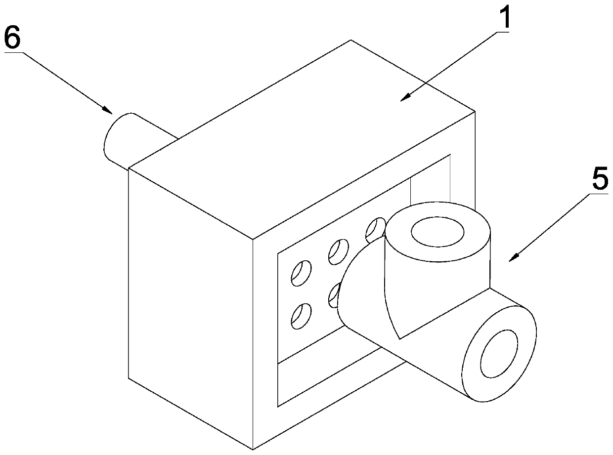
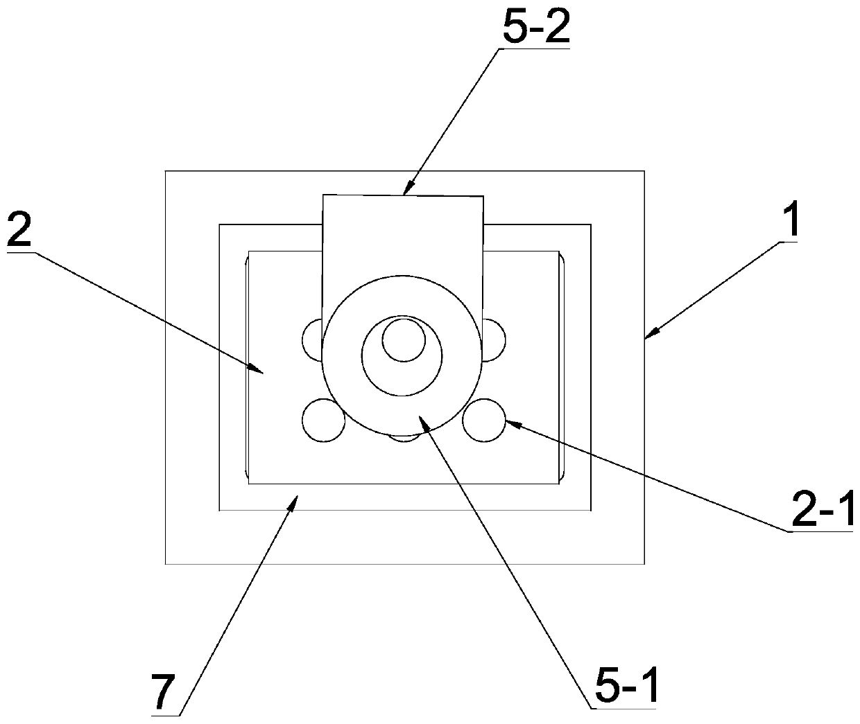
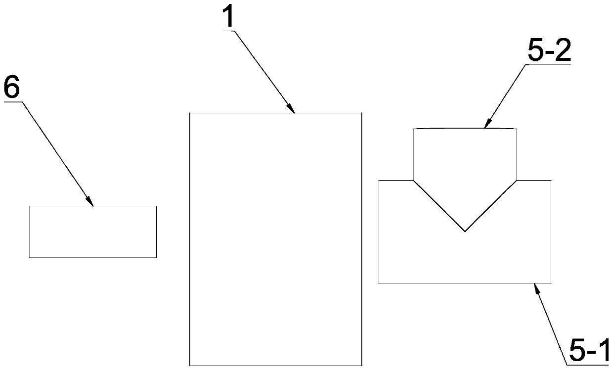
[0041] see Figure 1-Figure 5 , an electrolytic ozone generator in this embodiment includes a cavity 1, a positive electrode sheet 2 arranged inside the cavity 1, a negative electrode sheet 3, and a positive electrode sheet arranged between the positive electrode sheet 2 and the negative electrode sheet 3 A diaphragm 4 for proton exchange, a water inlet assembly 5 arranged at one end of the cavity 1 near the positive electrode sheet 2, and a spring 6 arranged at the end of the cavity 1 near the negative electrode sheet 3; wherein, the One end of the spring 6 acts on the negative plate 3, and the other end acts on the inner wall of the cavity 1; the water inlet end of the cavity 1 is provided with a water inlet, and the water outlet end is provided with a water outlet. The water inlet communicates with the water inlet assembly 5, the positive electrode piece 2 is close to the water inlet, and the negative electrode piece 3 is close to the water outlet. By setting the spring 6,...

Embodiment 2

[0061] Other structures in this embodiment are the same as in Embodiment 1, except that the first through hole 2-1 of the positive electrode sheet 2 and the second through hole 3-1 of the negative electrode sheet 3 are staggered from each other and axially Projections do not overlap. Adopting the above structure can effectively promote the surface contact area between the water body and the positive electrode sheet 2 or the negative electrode sheet 3, not only can promote the electrolysis efficiency but also can prepare ozone water with a higher concentration, so that the electrolysis product can be discharged circumferentially as soon as possible without inhibition, Improve cooling efficiency and reduce energy consumption.

Embodiment 3

[0063] see Figure 6-Figure 7 , the other structures in this embodiment are the same as those in Embodiment 1, except that the outlines of the cavity 1, the positive electrode sheet 2, the negative electrode sheet 3 and the diaphragm 4 are all circular, One side of the diaphragm 4 is parallel to the positive electrode sheet 2, and the other side of the diaphragm 4 is parallel to the negative electrode sheet 3; the positive electrode sheet 2 is provided with a circular first through hole 2-1, the number of the first through holes 2-1 is 6, one of which is set at the center of the positive electrode sheet 2, and the remaining 5 are in a circular array around the center of the positive electrode sheet 2; the negative electrode The sheet 3 is provided with a second through hole 3-1, the number of the second through hole 3-1 is 6, one of which is set at the center of the positive electrode sheet 2, and the remaining 5 surround the positive electrode sheet 2 The center of the circl...


PUM


Abstract

The invention discloses an electrolytic ozone generator, which comprises a cavity, electrode sheets and a diaphragm, wherein the electrode sheets and the diaphragm are arranged in the cavity, the electrode sheets comprise a positive electrode sheet and a negative electrode sheet, a water inlet and a water outlet are respectively formed in two ends of the cavity, one side surface of the diaphragm is parallel and opposite to the positive electrode sheet, the other side surface of the diaphragm is parallel and opposite to the negative electrode sheet, an annular flow guide channel is arranged among the periphery of the positive electrode sheet, the periphery of the negative electrode sheet, the periphery of the diaphragm and the inner wall of the cavity, a water flow distribution space is formed between the water inlet and the electrode sheet at the water inlet end, the water flow distribution space is communicated with the annular flow guide channel and a through hole in the electrode sheet at the water inlet end respectively, and the positive electrode sheet and the negative electrode sheet are electrically connected through water flowing through the positive electrode sheet and thenegative electrode sheet. The ozone generator can quickly take away the prepared ozone and improve the dissolved amount of the ozone in water, so that the ozone concentration is improved, the operation performance is stable, the energy consumption is low, and the heat dissipation of an electrode sheet is facilitated.

Description

technical field [0001] The invention relates to the technical field of ozone electrolysis devices, in particular to an electrolytic ozone generator. Background technique [0002] Ozone (O 3 ) is oxygen (O 2 ), which is a pale blue gas with a characteristic odor. Ozone is a strong oxidant, because of its strong oxidizing ability, it has a strong sterilization and disinfection effect. It will produce secondary pollution, so it is a green and environmentally friendly disinfectant. [0003] At present, in many countries and regions, ozone is widely used, such as in drinking water purification, medical water disinfection, air purification, food purification, sewage treatment, planting and breeding, paper bleaching and other industries and fields. However, due to the It is easy to self-decompose and not easy to store. Therefore, when using ozone, it is generally produced and used immediately. At present, the main ways to prepare ozone are corona method, electrolysis method, u...

Claims


Application Information

Patent Timeline
Patent Type & Authority Applications(China)
IPC IPC(8): C25B1/13C25B9/08C25B11/03C25B11/04C25B15/00C25B15/08C25B9/19
CPCC25B1/13C25B11/03C25B11/04C25B15/00C25B15/08C25B9/19C25B11/043C25B9/13C25B11/046
Inventor 钟建华张文英潘裕富
Owner GUANGZHOU DEPOSON ELECTRIC TECH
Learn More