
Plate compounding production line

A production line and plate technology, applied in the field of composite plate production line, can solve the problems of difficult control, high production cost, affecting the appearance of plates, etc., and achieve the effect of improving work efficiency

Active Publication Date: 2020-06-19
BEIJING NEW BUILDING MATERIALS PLC +1
View PDF4 Cites 9 Cited by
  • Summary
  • Abstract
  • Description
  • Claims
  • Application Information

AI Technical Summary

Problems solved by technology

[0003] The process of sheet film sticking production is cumbersome and complicated, making it difficult to fully realize automatic production. Many operations need to be completed manually, which means that the film sticking process needs to stop the production line many times for manual intervention, and cannot continue production, resulting in a long production cycle of the plate. The defects of high production cost and low production efficiency
At the same time, there are some problems that are not easy to control in the composite process of board and film paper, such as the poor film sticking effect caused by the position deviation of film paper, or the accumulation of film paper on the surface of the board, which will affect the quality of the board and cause the film paper to fall off easily during the application process. The beauty of the board even affects the service life of the board, and the improper control of the force applied during the pressing process of the film paper and the board damages the surface of the board and makes the board a waste board, etc.
[0004] At the same time, the current board film processing is to paste the composite film on the decorative surface of the board and the sides of both sides. The board produced by this film method has the problem that the end seams of adjacent boards are not beautiful enough during use. Affect the overall design layout of the board when it is used as a decorative board

Method used


Image

  • Plate compounding production line
  • Plate compounding production line
  • Plate compounding production line

Examples


Embodiment Construction

[0050] In order to make the purpose, technical solutions and advantages of the embodiments of the present invention clearer, the technical solutions in the embodiments of the present invention will be clearly and completely described below in conjunction with the drawings in the embodiments of the present invention. Obviously, the described embodiments It is a part of embodiments of the present invention, but not all embodiments. Based on the embodiments of the present invention, all other embodiments obtained by persons of ordinary skill in the art without making creative efforts belong to the protection scope of the present invention. It should be noted that, in the case of no conflict, the embodiments in the present application and the feature vectors in the embodiments can be combined arbitrarily with each other.

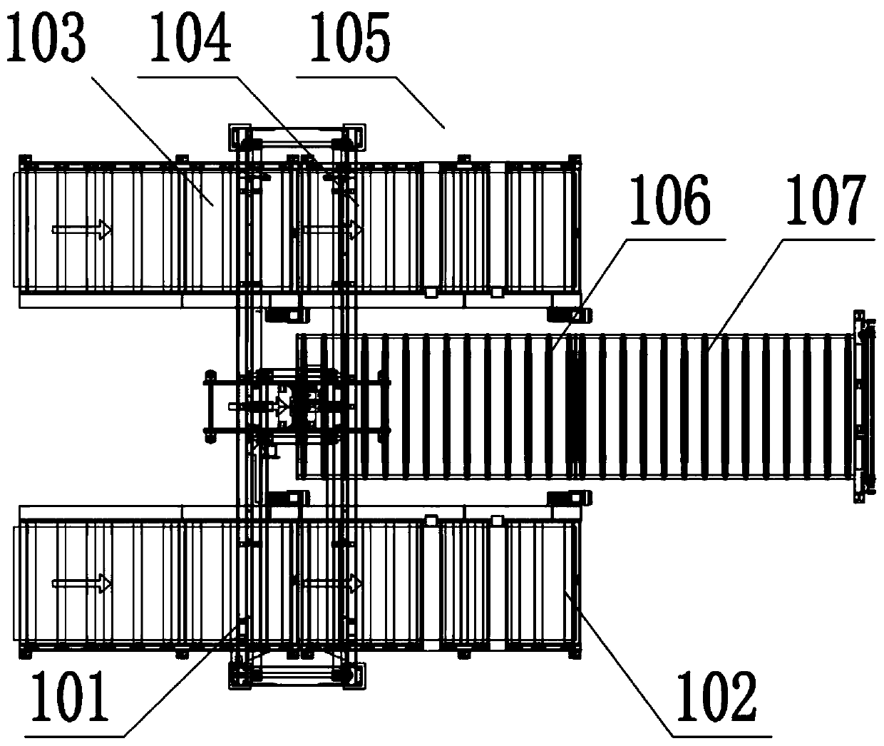
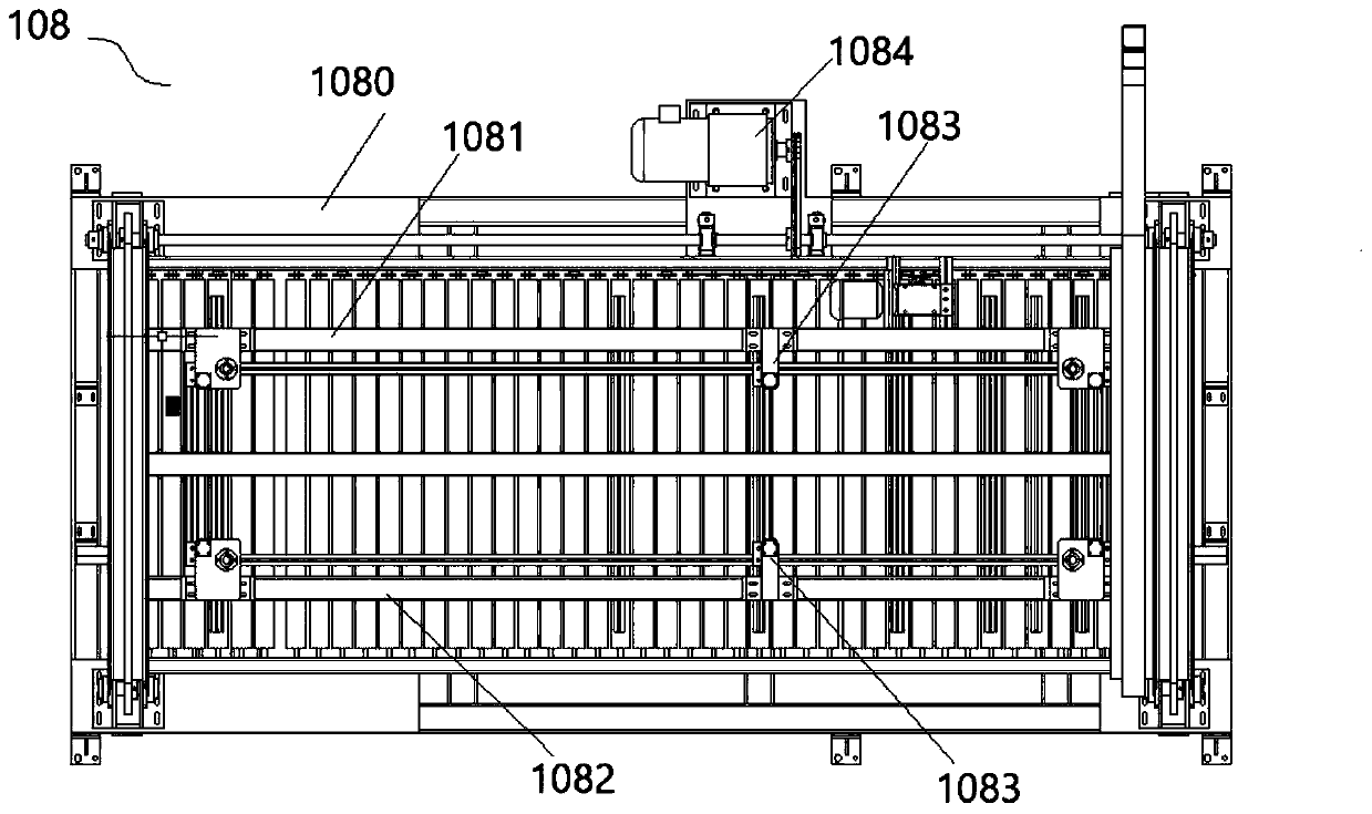
[0051] Such as figure 1 As shown, a sheet composite production line includes: a feeding system, a front turning device 108 connected to the feeding system to t...


PUM


Abstract

The invention discloses a plate compounding production line which comprises a feeding system, a front plate turnover system connected with the feeding system, a compounding system connected with the front plate turnover system and a discharging system connected with the compounding system. The compounding system comprises three-side compounding equipment, tracking cutting equipment connected withthe three-side compounding equipment, four-corner cutting equipment connected with the tracking cutting equipment through a first steering conveying roller set, and five-side compounding equipment directly connected with the four-corner cutting equipment. The three-side compounding equipment bonds the rolled composite film with the surface and the two side surfaces of the plate; the tracking cutting equipment cuts the composite films at the two ends of the plate to reserve the composite films with the preset length for five-side compounding at the two ends of the plate, the four-corner cuttingequipment cuts the redundant composite films at the two ends of the plate to cut the composite films into shapes suitable for five-side compounding, and the five-side compounding equipment presses the composite films at the two ends of the plate and the two end faces of the plate.

Description

technical field [0001] The invention relates to the technical field of composite board production equipment, in particular to a composite board production line. Background technique [0002] During the processing of building or furniture boards such as wood boards and gypsum boards, film is usually attached to the surface of the boards. The surface of the boards can improve the performance of the boards, such as moisture-proof, waterproof, fire-proof, flame-retardant, high-temperature resistance, and improved deformation resistance. Make the board more beautiful and rich in appreciation value. [0003] The process of sheet film sticking production is cumbersome and complicated, making it difficult to fully realize automatic production. Many operations need to be completed manually, which means that the film sticking process needs to stop the production line many times for manual intervention, and cannot continue production, resulting in a long production cycle of the plate. ...

Claims


Application Information

Patent Timeline
Patent Type & Authority Applications(China)
IPC IPC(8): B32B37/00B32B37/10B32B37/12B32B38/00B32B38/18B27D1/08B27D5/00B28D1/00B28D7/00
CPCB32B37/0046B32B37/10B32B37/1284B32B38/0004B32B38/18B27D1/08B27D5/00B27D5/006B28D1/00B28D7/00
Inventor 王兵杨正波董占波汪艳林白纪新李永林刘明海
Owner BEIJING NEW BUILDING MATERIALS PLC
Learn More