A circular fiber desktop board edging machine
A desktop board and edging machine technology, which is applied to machine tools suitable for grinding the edge of workpieces, parts of grinding machine tools, grinding machines, etc., can solve the problems of low work efficiency of manual edging, avoid shaking and improve work efficiency , the effect of low technical requirements
- Summary
- Abstract
- Description
- Claims
- Application Information
AI Technical Summary
Problems solved by technology
Method used
Image
Examples
Embodiment 1
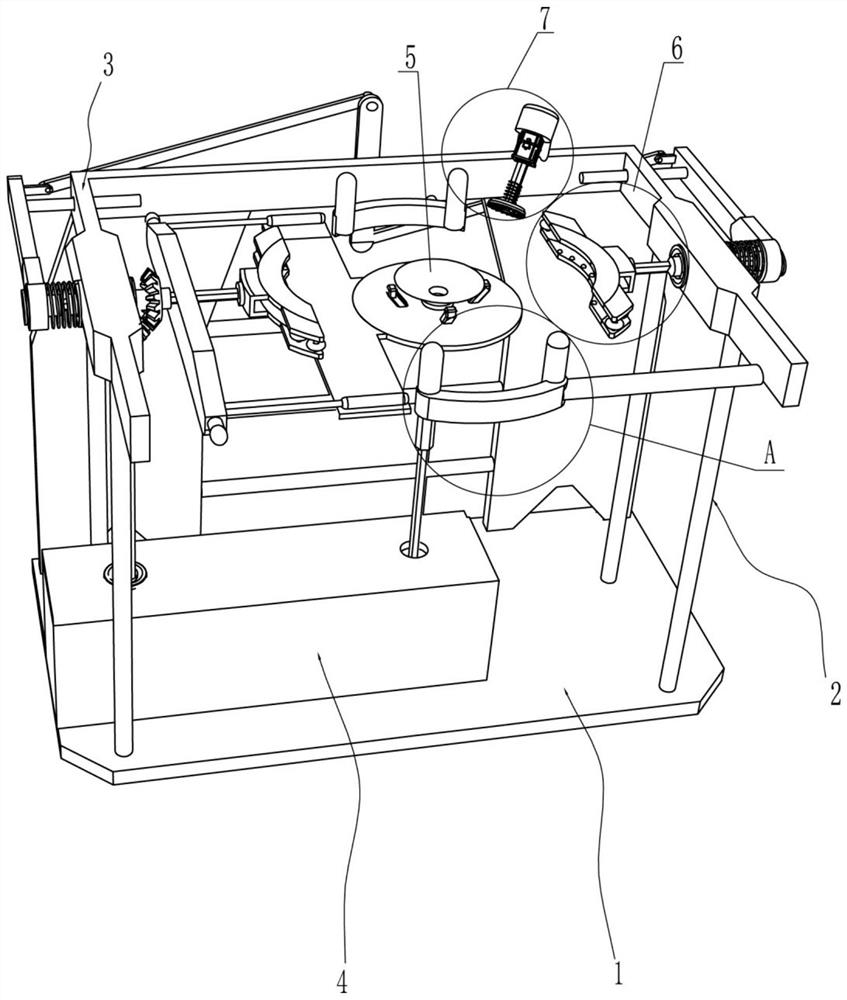
[0024] A circular fiber tabletop board edger, such as figure 1 , figure 2 , Figure 4 , Figure 5 and Figure 6 As shown, it includes a base 1, a support frame 2, an installation frame 3 and an installation box 4, the top of the base 1 is connected with the support frame 2 and the installation box 4, the top of the support frame 2 is connected with the installation frame 3, and the installation frame 3 is connected by bolts The method is connected with the support frame 2, and also includes a rotating assembly 5, a clamping assembly 6 and an edge grinding assembly 7. The installation box 4 is provided with a rotating assembly 5, and the rotating assembly 5 is used to drive the fiber round table to rotate. The installation frame 3 is provided with There are clamping assembly 6 and edging assembly 7.
[0025] The rotating assembly 5 includes a reduction motor 51, a sector gear 52, a first rhombic rod 53, a drive gear 54, a first rhombic sleeve 55, a support plate 56, a suct...
Embodiment 2
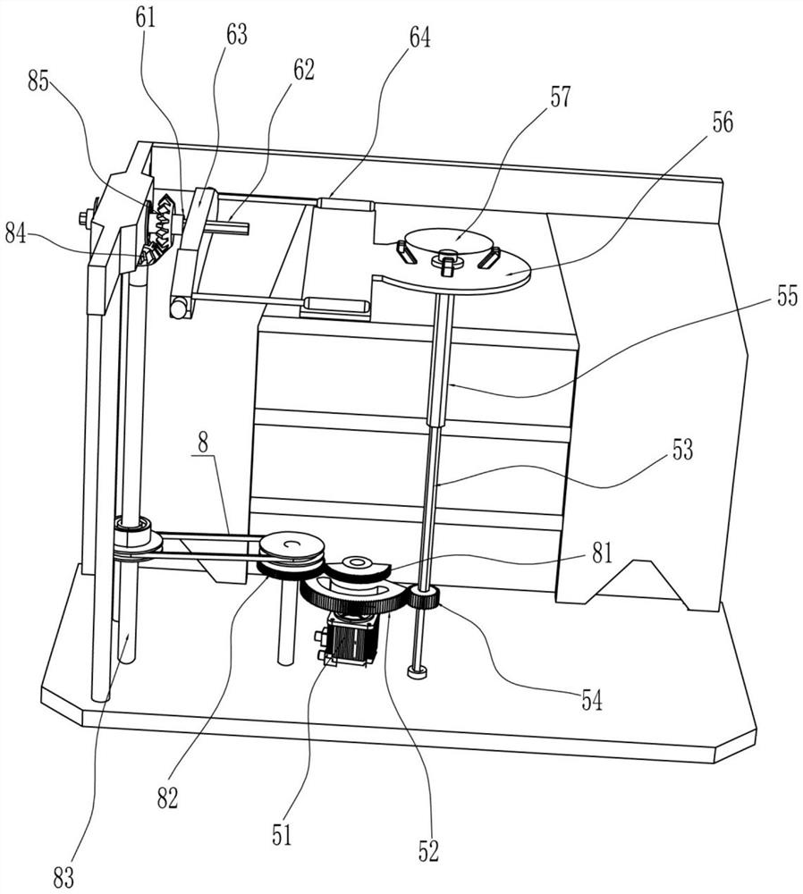
[0030] On the basis of Example 1, such as figure 2 As shown, an automatic transposition assembly 8 is also included, and the automatic transposition assembly 8 includes a semicircular gear 81, a transmission gear 82, a rotating shaft 83, a first bevel gear 84 and a second bevel gear 85, and the output shaft of the reduction motor 51 is also A semicircular gear 81 is connected, and the bottom of the installation frame 3 is rotatably connected with a transmission gear 82 and a rotating shaft 83. The transmission gear 82 meshes with the semicircular gear 81, and the transmission gear 82 is connected with the rotating shaft 83. The top of the rotating shaft 83 is connected with a first bevel gear 84. , the second rhombic sleeve 61 is connected with a second bevel gear 85, the second bevel gear 85 is connected with the second rhombic sleeve 61 through an interference connection, and the second bevel gear 85 is used to drive the second rhombic sleeve 61 rotates, and the second beve...
Embodiment 3
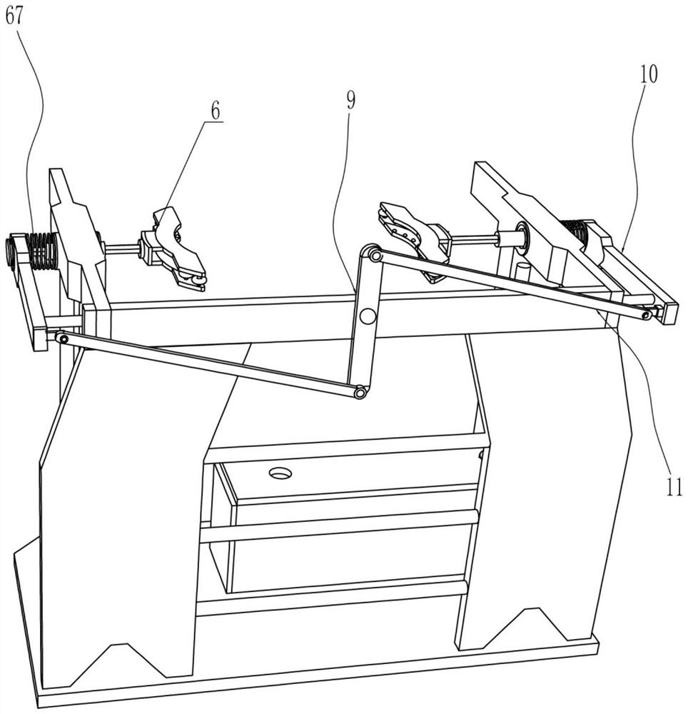
[0033] On the basis of Example 2, such as image 3 As shown, it also includes a rotating rod 9, a sliding rod 10 and a connecting rod 11. The rear side of the mounting frame 3 is hingedly connected with a rotating rod 9, and the two ends of the rear side of the rotating rod 9 are hingedly connected with a connecting rod 11. Two connecting rods 11 Both ends are hingedly connected with a sliding rod 10 , the connecting rod 11 is used to drive the sliding rod 10 to move, the sliding rod 10 is slidingly matched with the mounting frame 3 , and the second diamond rod 62 is connected with the sliding rod 10 in a rotational manner.
[0034] When the first rhombic rods 53 on both sides need to be pulled away from each other, one of the sliding rods 10 can be pulled to move away from the installation frame 3. When the sliding rod 10 moves, the connecting rod 11 drives the rotating rod 9 to swing along the hinge point. The rotating rod 9 drives another sliding rod 10 to move away from th...
PUM
 Abstract
Description
Claims
Application Information
 - Generate Ideas
- Intellectual Property
- Life Sciences
- Materials
- Tech Scout
- Unparalleled Data Quality
- Higher Quality Content
- 60% Fewer Hallucinations
Browse by: Latest US Patents, China's latest patents, Technical Efficacy Thesaurus, Application Domain, Technology Topic, Popular Technical Reports.
© 2025 PatSnap. All rights reserved.Legal|Privacy policy|Modern Slavery Act Transparency Statement|Sitemap|About US| Contact US: help@patsnap.com


