Mechanical plate grinding device with overturning function
A technology of turning mechanism and plate, applied in the direction of grinding drive device, grinding machine parts, machine tools suitable for grinding workpiece plane, etc. problems, to achieve the effect of improving work efficiency, improving the grinding range, and ensuring the grinding effect
- Summary
- Abstract
- Description
- Claims
- Application Information
AI Technical Summary
Problems solved by technology
Method used
Image
Examples
Embodiment 1
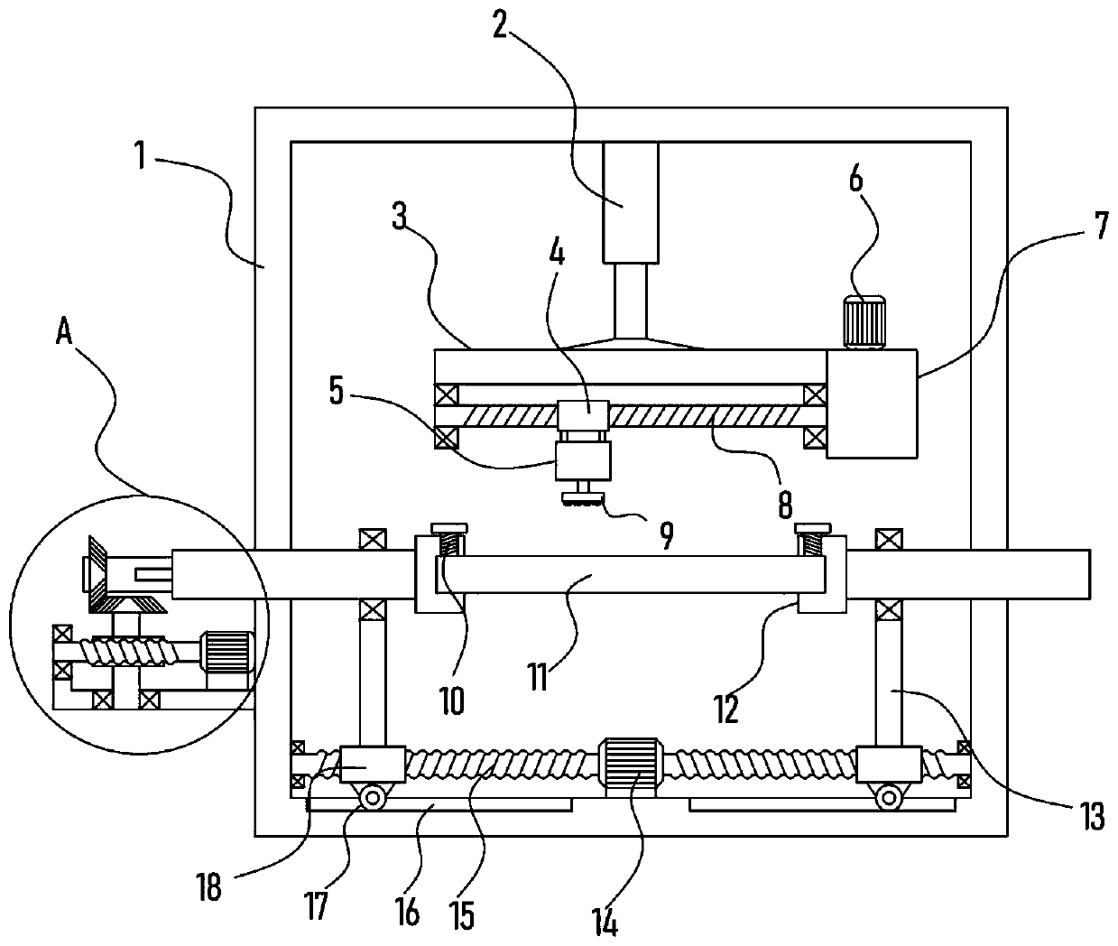
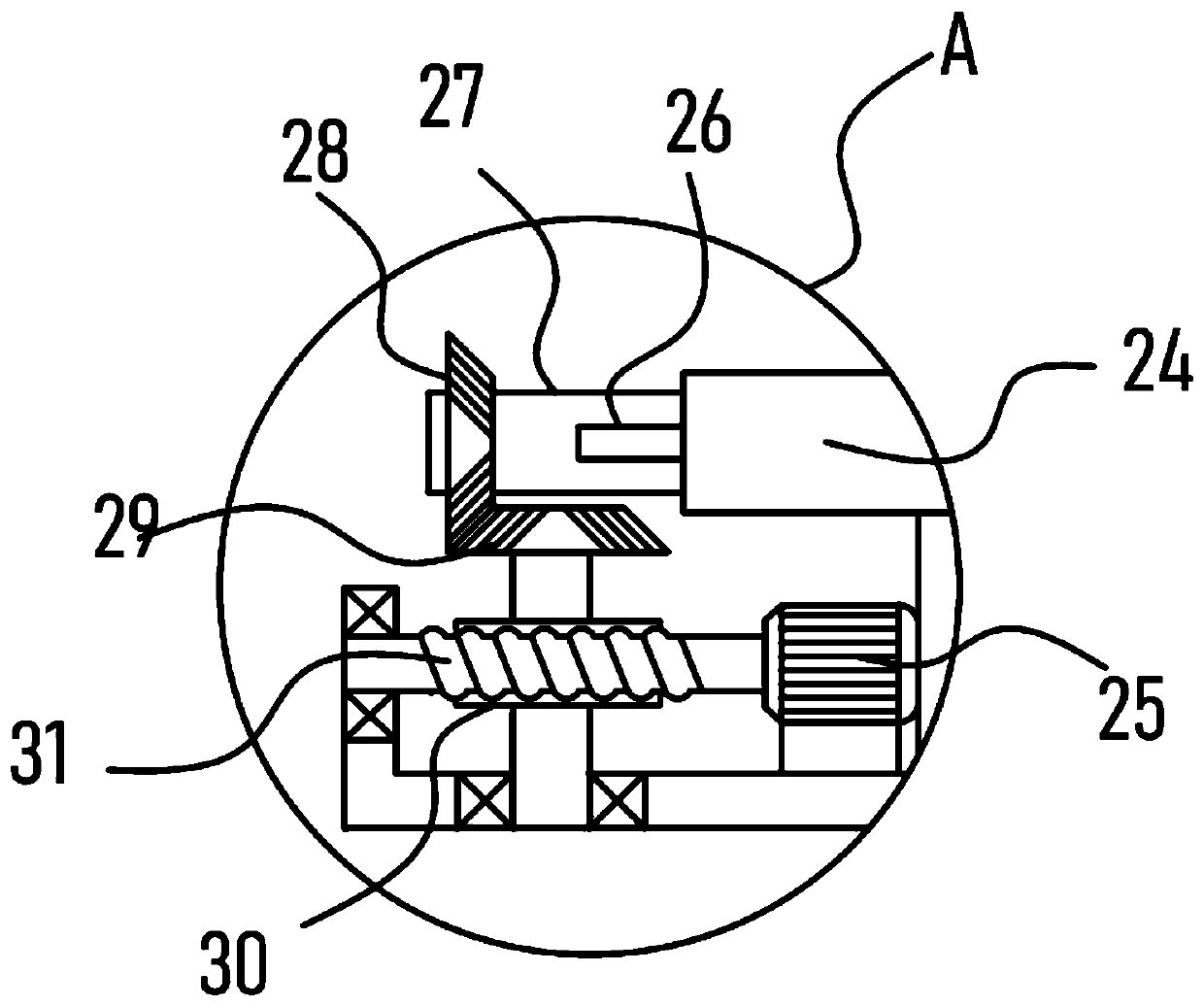
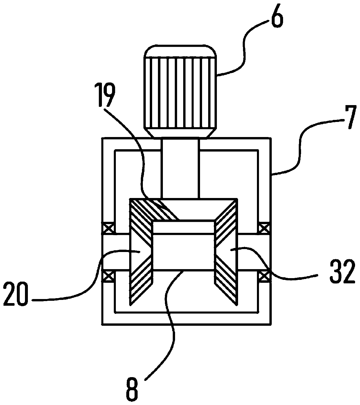
[0026] see Figure 1-5 , a mechanical plate grinding device with a flipping function, comprising a support frame 1, an electric push rod 2 is vertically fixed on the inner top of the support frame 1, and a horizontal lifting frame 3 is connected to the lower end of the electric push rod 2, and the bottom of the lifting frame 3 A grinding mechanism for grinding the plate 11 is provided. A steering box 7 is fixed on the lifting frame 3. A translation mechanism for driving the grinding mechanism to move laterally is provided in the steering box 7. A pair of For clamping the pallets 12 of the panels 11 , the support frame 1 is provided with an adjustment mechanism for driving the two pallets 12 to move toward each other, and the support frame 1 is provided with an overturning mechanism for driving the pallets 12 to rotate.
[0027] A pair of clamping plates 12 provided in the device clamp and fix the plate 11 to ensure its stability in the grinding process. The set grinding mechan...
Embodiment 2
[0032] On the basis of Embodiment 1, in addition, the device is provided with an adjustment mechanism, including a biaxial motor 14, and the two output shafts of the biaxial motor 14 are coaxially fixed with a threaded screw 15 with opposite helical directions. A screw mandrel cover 18 is sleeved, and a support plate 13 is vertically fixed on the screw mandrel cover 18, and a drive sleeve 24 fixed to the clamp plate 12 is pivotally connected to the support plate 13, and the drive sleeve 24 slides with the support frame 1 Connection, the clamping plate 12 is a U-shaped structure, and the locking stud 10 for locking the plate 11 is threaded on the clamping plate 12 .
[0033] The biaxial motor 14 drives the screw mandrel 15 to rotate, and the screw mandrel 15 drives the screw mandrel block 18 on it to move toward each other. At this time, the support plate 13 drives the transmission sleeve 24 to move toward each other, thereby realizing the opposite movement of the clamping plate...
PUM
 Abstract
Description
Claims
Application Information
 - R&D
- Intellectual Property
- Life Sciences
- Materials
- Tech Scout
- Unparalleled Data Quality
- Higher Quality Content
- 60% Fewer Hallucinations
Browse by: Latest US Patents, China's latest patents, Technical Efficacy Thesaurus, Application Domain, Technology Topic, Popular Technical Reports.
© 2025 PatSnap. All rights reserved.Legal|Privacy policy|Modern Slavery Act Transparency Statement|Sitemap|About US| Contact US: help@patsnap.com


