Laser cutting machine

A laser cutting machine and laser cutting technology, applied in the laser field, can solve the problems of high processing cost, increased product processing cost, cumbersome operation, etc., to improve the time for clamping or taking out the workpiece, good laser cutting effect, and improve work efficiency Effect

Pending Publication Date: 2020-06-19
北京奥峰铭金属制品有限公司
View PDF7 Cites 13 Cited by
  • Summary
  • Abstract
  • Description
  • Claims
  • Application Information

AI Technical Summary

Problems solved by technology

[0004] The existing laser inner wall processing technology uses focusing at the end point. Since the focusing lens is used, the focusing lens needs to be replaced each time for parts of different sizes, which increases the product processing cost and is cumbersome to operate.
[0005] Due to the cutting of the rotary workpiece, the laser focus position must be accurate, and the laser beam must always be perpendicular to the surface of the rotary body, which limits the movement space of the industrial robot and is prone to dead spots. At the same time, it is difficult to ensure the laser focus during the cutting process. Keeping constant and clamping, picking and placing rotating workpieces is more complicated
Therefore, it is difficult to ensure the quality and efficiency of laser processing of rotary workpieces, and the processing cost is also high

Method used


Image

  • Laser cutting machine
  • Laser cutting machine
  • Laser cutting machine

Examples


Embodiment Construction

[0032] The present invention will be described in further detail below in conjunction with the accompanying drawings.

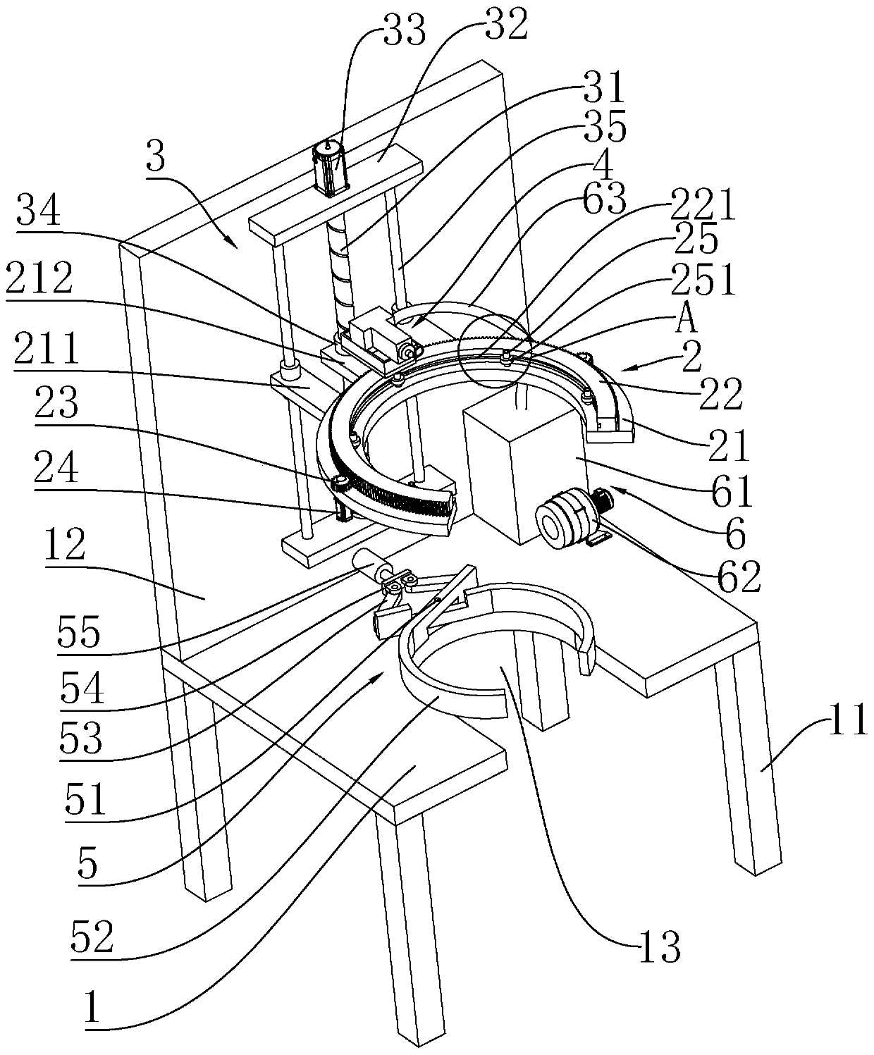
[0033] Such as figure 1 As shown, a laser cutting machine includes a platform 1, a support rod 11 is provided under the platform 1, a vertical plate 12 is provided on the rear side of the platform 1, and a vertical plate 12 is provided on the vertical plate 12 to drive the rotary cutting platform 2 to move up and down. The lifting mechanism 3, the rotary cutting platform 2 includes an annular supporting plate 21 with an open front side, the upper end of the supporting plate 21 is provided with an annular ring gear 22 with an opening, and the ring gear 22 is provided with a ring gear 22 along its circumferential direction. The gears 23 that are meshed and arranged oppositely, each gear 23 is respectively connected with the first driving motor 24 fixed below the supporting plate 21, the other side of the ring gear 22 is arranged at intervals along its circumfer...


PUM


Abstract

The invention relates to a laser cutting machine. The laser cutting machine comprises a platform, supporting rods are arranged under the platform, a vertical plate perpendicular to the platform is arranged on the rear side of the platform, a lifting mechanism for driving the upper and lower motion of a rotary cutting platform is arranged on the vertical plate, and the rotary cutting platform comprises a circular supporting plate with a front side opening. A circular gear ring with an opening is arranged at the upper end of the supporting plate, gears meshing with the gear ring and oppositely arranged are arranged on one side of the gear ring in the circumferential direction, and each gear is separately connected to a first drive motor. A plurality of rollers abutting against the gear ringand and connected to the supporting plate are arranged on the other side of the gear ring at intervals in the circumferential direction, the gear ring can perform circumferential rotation around a center of the gear ring, a laser cutting assembly is fixedly connected to the upper end of the gear ring, a circular hole with a front side opening is formed in the platform below the supporting plate, and a clamping mechanism is arranged above the circular hole. The laser cutting machine can be applied to cutting of workpieces of different size revolving bodies, a laser beam is accurate in focusing,the perpendicularity is good, the cutting effect is good, the clamping and taking workpiece is convenient and quick, and the processing cost is low.

Description

technical field [0001] The invention relates to the field of laser technology, in particular to a laser cutting machine. Background technique [0002] Laser cutting is to irradiate the workpiece with a focused high-power-density laser beam, so that the irradiated product is rapidly melted or vaporized or ablated or reaches the ignition point, thereby realizing the processing of the workpiece. [0003] At present, the laser cutting of the outer surface of the rotary workpiece generally uses a turntable to fix the rotary workpiece, and the laser cutting head is used to control the laser cutting head to perform laser cutting on the outer surface of the rotary body. [0004] The existing laser inner wall processing technology uses focusing at the end point. Since the focusing lens is used, the focusing lens needs to be replaced each time for parts of different sizes, which increases the product processing cost and is cumbersome to operate. [0005] Due to the cutting of the rot...

Claims


Application Information

Patent Timeline
IPC IPC(8): B23K26/02B23K26/142B23K26/38B23K26/70
CPCB23K26/02B23K26/38B23K26/142B23K26/702
Inventor 李金贵
Owner 北京奥峰铭金属制品有限公司
Why Eureka
Try Eureka