
Full-automatic punching shearing machine

A punching and shearing machine, fully automatic technology, used in conveyors, metal processing equipment, feeding devices, etc., can solve the problems of punching and shearing machine failure, affecting punching and shearing processing quality and processing efficiency, etc. The number of small maintenance and adjustment of the blank position, the effect of saving manpower and material resources

Inactive Publication Date: 2020-06-19
阎勇
View PDF0 Cites 0 Cited by
  • Summary
  • Abstract
  • Description
  • Claims
  • Application Information

AI Technical Summary

Problems solved by technology

[0004] In order to make up for the deficiencies of the existing technology, to solve the problem of slipping between the blank and the transmission device during the automatic feeding process when the weight of the blank is too large, so that when the transmission device runs a fixed working distance, the blank is due to Slipping caused it to fail to reach the processing position, which caused the failure of the punching and shearing machine and affected the quality and efficiency of punching and shearing. An elastic coupling proposed by the present invention

Method used


Image

  • Full-automatic punching shearing machine
  • Full-automatic punching shearing machine
  • Full-automatic punching shearing machine

Examples


Embodiment approach

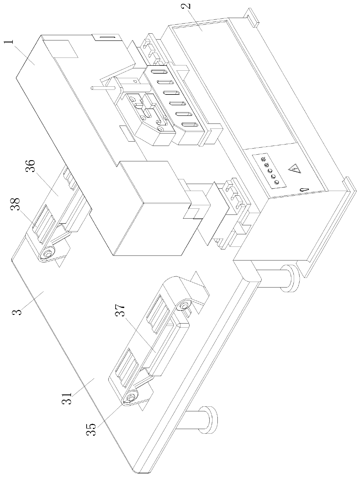
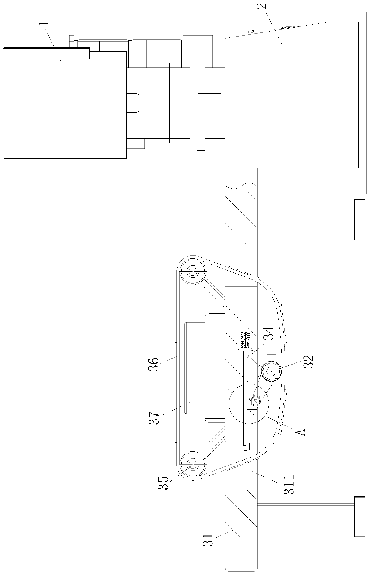
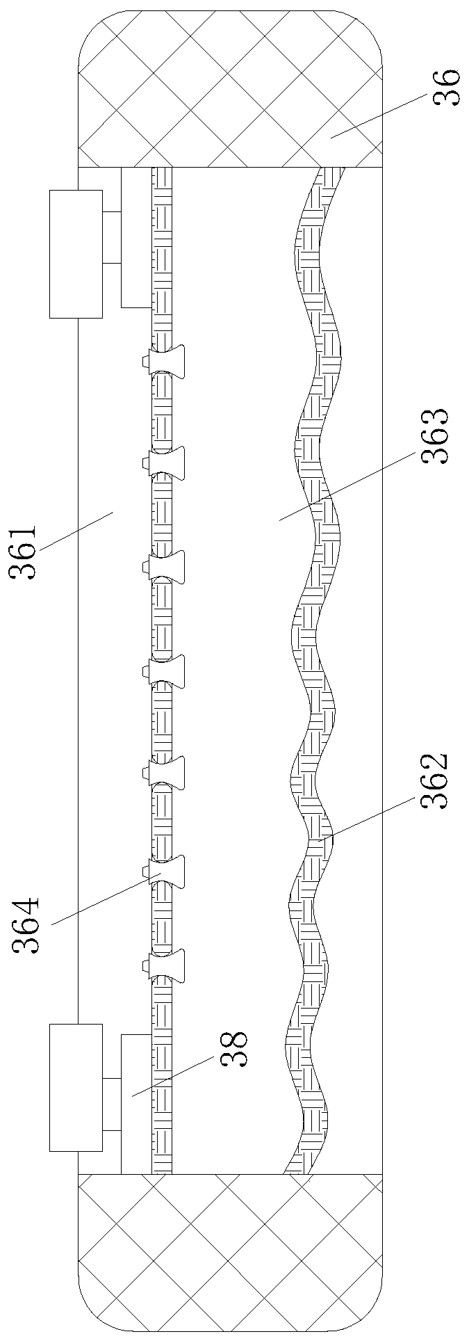
[0024] As an embodiment of the present invention, the push rod 34 is composed of a main rod 342 and an elastic rod 343; the elastic rod 343 is symmetrically installed at the end of the main rod 342, and the end of the elastic rod 343 is provided with a rolling ball 344, and Elastic bar 343 is provided with wave-shaped projection on the side wall that contacts with transmission belt 36; By the cooperation of main bar 342, elastic bar 343 and rolling ball 344, reduce the jacking force of vertical its side wall that transmission belt 36 suffers; , when the staff needs to process the blank through the punching and shearing machine, the staff first places the blank on the transmission belt 36, and at this time, the motor 32 is energized, so that the rotation of the output end of the motor 32 drives the transmission belt 36 to rotate, thereby turning the transmission belt The blank on the 36 is transported to the punching and shearing table 1. At this time, the punching and shearing ...


PUM


Abstract

The invention relates to the technical field of punching shearing machining, in particular to a full-automatic punching shearing machine. The full-automatic punching shearing machine comprises a punching shearing platform, a transmission unit and a workbench, wherein the punching shearing platform is installed on the workbench, the transmission unit is installed at one position close to the workbench and comprises a base, motors, stirring wheels, top rods, supporting wheels, transmission belts and electromagnetic strips, the base is installed at one position close to the workbench, the surfaceof the base is symmetrically provided with through holes, and the side wall of the bottom end of the base is provided with first chutes, and the motors are installed to the base side walls close to the first chutes. According to the full-automatic punching shearing machine, by means of coordination of the punching shearing platform, the transmission unit and the workbench, the fixing function onblanks in the transportation process is enhanced, the friction force on the blanks on the surfaces of the transmission belts is enhanced, the situation that the blanks slide on the surfaces of the transmission belts due to the own gravity of the blanks is further avoided, so that normal work of the punching shearing machine is guaranteed, and the work efficiency of the punching shearing machine isimproved.

Description

technical field [0001] The invention relates to the technical field of punching and shearing, in particular to a fully automatic punching and shearing machine. Background technique [0002] The punching and shearing process adopts a C-shaped open body, and the body can be approached from three sides, which is convenient for maintenance; the weight of the whole machine is light, the inertia is small when moving, and it is easy to obtain a large acceleration, which effectively improves labor productivity. Adopt hydraulic pressure punching process. The mold adopts a linear structure, and the cylinder pushes the module mechanism to select different molds to participate in stamping, which speeds up the mold selection speed and improves work efficiency; the integral upper and lower mold cavities are processed in pairs to ensure the concentricity of the mold and greatly extend the use of the mold Long service life; the mold adopts a nested structure, which is convenient for mainte...

Claims


Application Information

Patent Timeline
Patent Type & Authority Applications(China)
IPC IPC(8): B21D43/12B65G15/58
CPCB21D43/12B65G15/58
Inventor 阎勇杨胜张家俊
Owner 阎勇
Learn More