Bunching arrangement device for optical fiber branching device

An optical fiber splitter and finishing device technology, applied in the directions of light guides, optics, instruments, etc., can solve the problems of scattered distribution of optical fibers, poor equipment contact, trouble, etc., to facilitate maintenance and inspection, and prevent equipment from poor contact.

Inactive Publication Date: 2020-06-16
洪丽雅
View PDF7 Cites 5 Cited by
  • Summary
  • Abstract
  • Description
  • Claims
  • Application Information

AI Technical Summary

Problems solved by technology

[0004] The invention provides a bundle arrangement device for an optical fiber splitter, which effectively solves the problem that most of the places where the optical fiber splitter and the optical fiber are connected do not have a protective structure. When the optical fiber is pulled, the connection between the optical fiber and the optical fiber splitter The place is easily damaged, resulting in poor contact of the equipment, and most of the optical fibers are scattered on the optical fiber splitter. The staff need to pay attention to the investigation during maintenance and inspection, which is more troublesome.

Method used


Image

  • Bunching arrangement device for optical fiber branching device
  • Bunching arrangement device for optical fiber branching device
  • Bunching arrangement device for optical fiber branching device

Examples


Embodiment

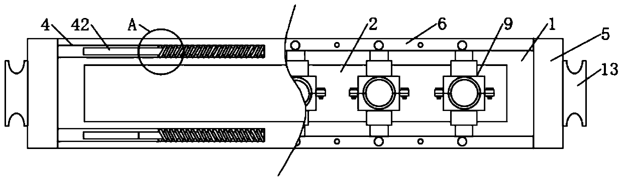
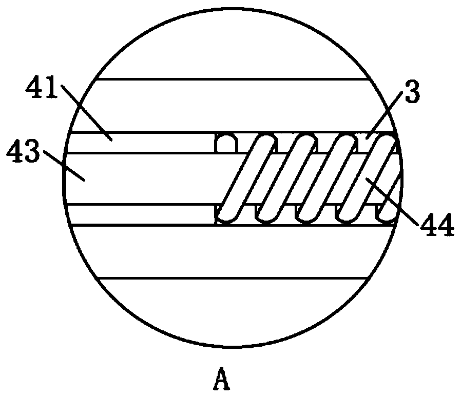
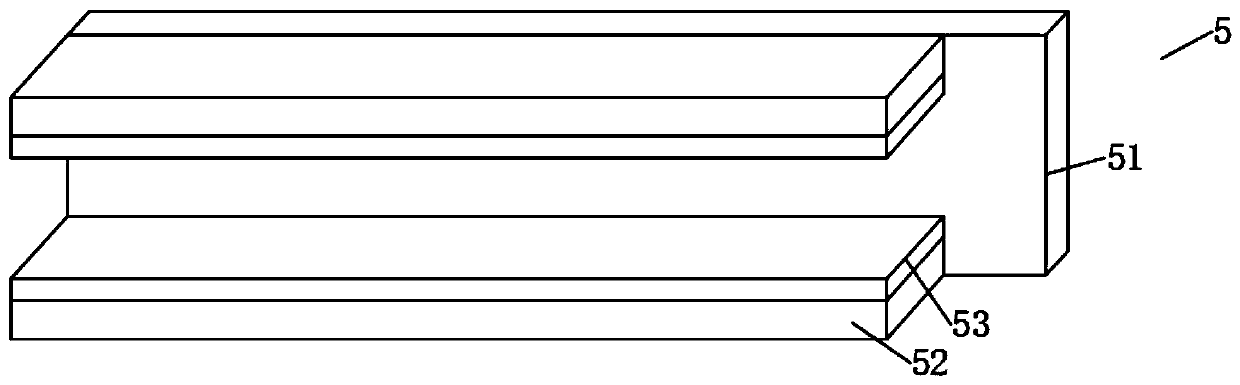
[0026] Example: such as Figure 1-5 As shown, a harness arrangement device for an optical fiber splitter of the present invention includes a fixing plate 1, a through slot 2 penetrates through the middle of the front of the fixing plate 1, and the upper and lower sides of the side walls of the fixing plate 1 Both ends are provided with telescopic grooves 3, the interior of the telescopic groove 3 is installed with a telescopic mechanism 4, both sides of the fixed plate 1 are installed with splints 5, the middle of the splint 5 away from the fixed plate 1 A pull plate 13 is fixedly connected, and the upper and lower ends of the front surface of the fixed plate 1 are fixedly connected with a mounting plate 6, and the two mounting plates 6 are provided with sliding grooves 7 on the sides close to each other. A number of insertion holes 10 are provided on the inner wall of one side of the fixing plate 1, and the inner wall of the sliding groove 7 far away from the fixing plate 1 is...


PUM


Abstract

The invention discloses a bunching arrangement device for an optical fiber branching device. The device comprises a fixed plate, and a through groove penetrates through the middle of the front surfaceof the fixed plate; telescopic grooves are formed in the upper and lower ends of the two side walls of the fixed plate; telescopic mechanisms are mounted in the telescopic grooves; clamping plates are mounted on the two sides of the fixed plate; pull plates are fixedly connected to the middles of the sides, away from the fixing plates, of the clamping plates; mounting plates are fixedly connectedto the upper and lower ends of the front surface of the fixed plate; and sliding grooves are formed in the sides, close to the middle of the fixing plate, of the mounting plates; and a plurality of inserting holes are formed in the inner walls of the sides, close to the fixing plate, of the sliding grooves 7. According to the bunching arrangement device, the bunching mechanisms are arranged on the fixed plate, and optical fibers are clamped through the first chucks and the second chucks of the bunching mechanisms in the using process; meanwhile, the positions of the first chucks and the positions of the second chucks are fixed through the plug pins, the optical fibers are prevented from being interwoven, and therefore the optical fibers are arranged, and workers can maintain and check theoptical fibers conveniently.

Description

Technical field [0001] The invention relates to a wire harness arrangement device, in particular to a wire harness arrangement device for an optical fiber splitter, belonging to the technical field of optical fiber splitters. Background technique [0002] Optical fiber splitter is a device used to split and combine light wave energy. It distributes the light energy transmitted in an optical fiber to two or more optical fibers according to a predetermined ratio, or combines the light energy transmitted in multiple optical fibers into one optical fiber. [0003] At present, most of the places where the fiber optic splitter and the fiber are connected are not equipped with a protective structure. When the fiber is pulled, the place where the fiber and the fiber splitter are connected is easily damaged, resulting in poor contact of the equipment, and most of the fibers are scattered in the fiber splitter. On the other hand, staff need to pay attention to troubleshooting during mainten...

Claims


Application Information

Patent Timeline
Patent Type & Authority Applications(China)
IPC IPC(8): G02B6/44
CPCG02B6/4431
Inventor 洪丽雅
Owner 洪丽雅
Why Eureka
Try Eureka