
Buoy device for marine environment monitoring and monitoring method thereof

A marine environment monitoring and buoy device technology, which is applied in the direction of measuring devices, buoys, transportation and packaging, etc., can solve the problems of insufficient power of marine monitoring buoy devices, affecting the normal operation of the device, and large errors in monitoring results. It achieves superior fixed performance, Excellent stabilization effect and easy anchoring effect

Active Publication Date: 2020-06-16
SOUTH CHINA INST OF ENVIRONMENTAL SCI MEP
View PDF8 Cites 16 Cited by
  • Summary
  • Abstract
  • Description
  • Claims
  • Application Information

AI Technical Summary

Problems solved by technology

[0004] The existing buoy devices used to monitor the marine environment are not stable enough, and are easily swayed or tipped by the impact of wind and waves, thus affecting the normal operation of the device; when monitoring the quality of ocean water, different monitoring and analysis of water quality in sea areas at different depths , the monitoring results have a large error; the power supply device usually uses a solar power generation device. When encountering continuous rainy weather, the power of the marine monitoring buoy device will be insufficient, thus affecting its normal work.

Method used


Image

  • Buoy device for marine environment monitoring and monitoring method thereof
  • Buoy device for marine environment monitoring and monitoring method thereof
  • Buoy device for marine environment monitoring and monitoring method thereof

Examples


Embodiment 1

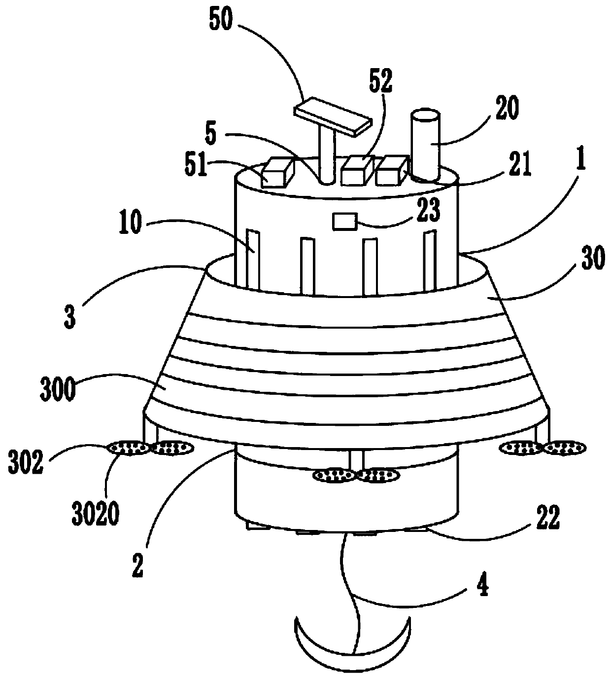
[0036] Such as figure 1 The shown buoy device for marine environment monitoring mainly includes a buoy body 1 with 9 vertical grooves 10 uniformly arranged on the outer side wall along the circumferential direction, a monitoring element 2 arranged on the buoy body 1 and The stabilizing collar mechanism 3 outside the buoy main body 1, the anchoring mechanism 4 provided at the bottom end of the buoy main body 1, and the power supply 5 for supplying power to various electrical components;

[0037] The monitoring element 2 includes an anemometer 20 arranged on the buoy body 1, a signal transceiver element 21 for connecting with an external control device, a water body collecting element 22 for collecting marine water, and a micro-controller for controlling the normal operation of various electrical elements. The water body collection element 22 adopts the layered water body automatic collector produced by Beijing Zhonghe Technology Co., Ltd., which is mainly used to collect water qual...

Embodiment 2

[0045] Embodiment 2 is basically the same as embodiment 1, except that:

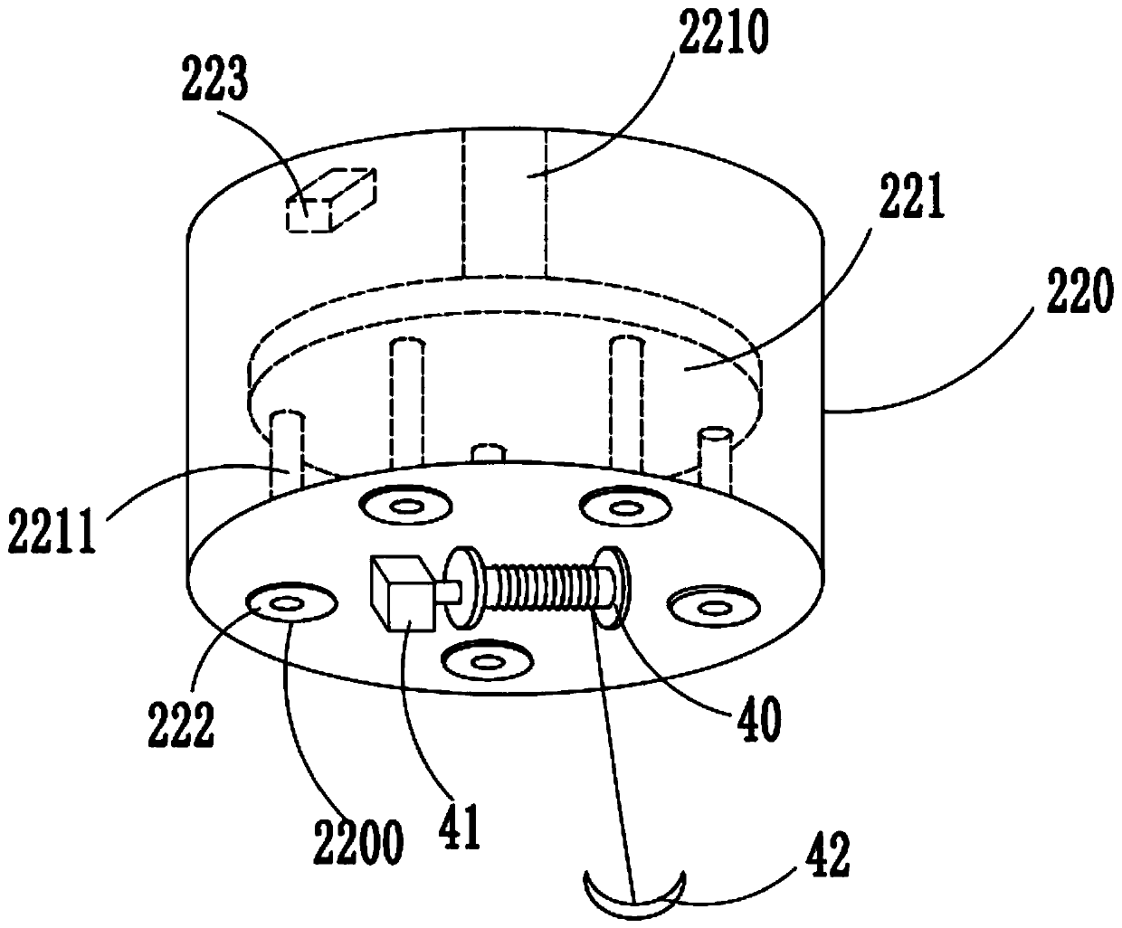
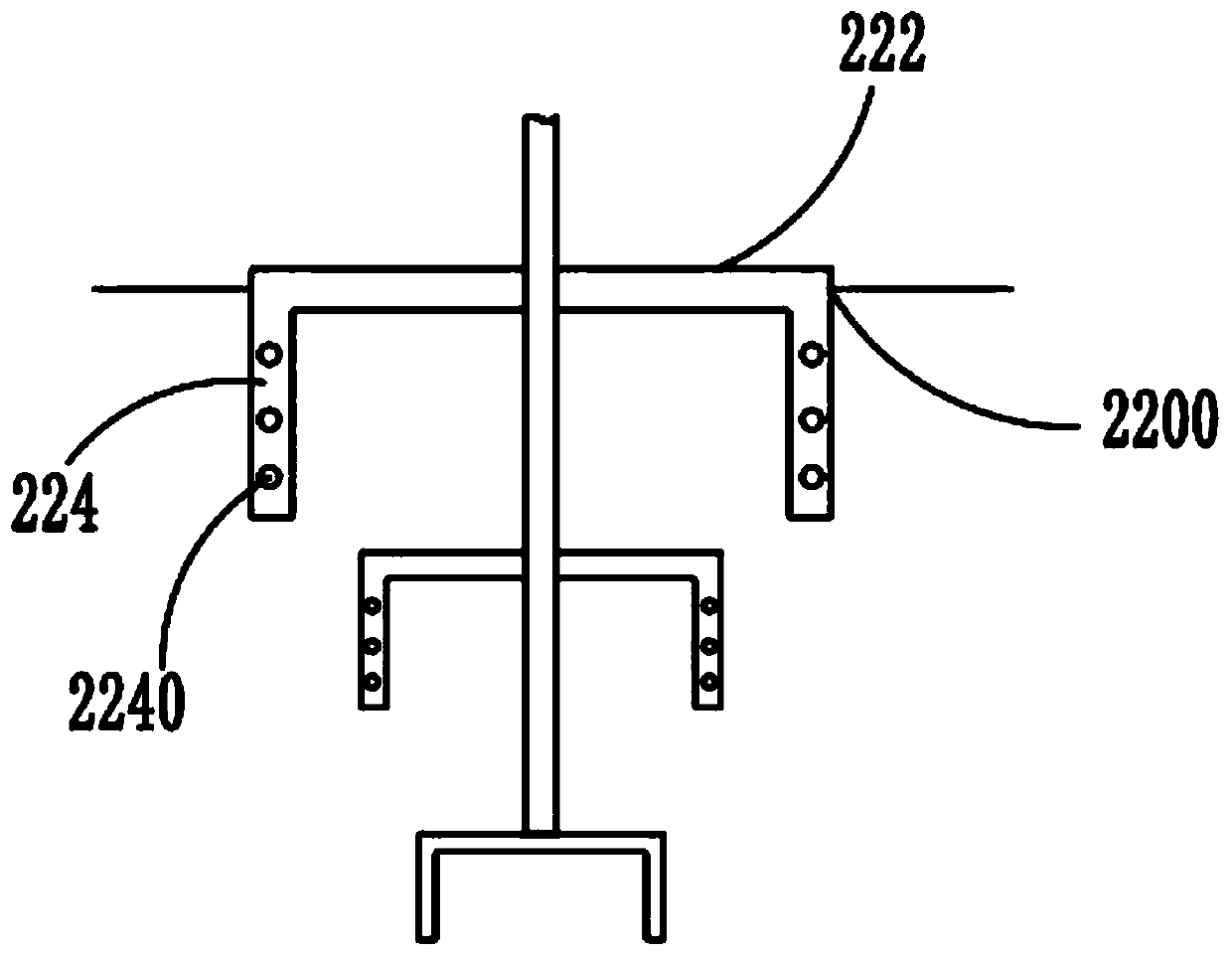
[0046] Such as figure 2 As shown, the water collection element 22 includes a collection tray 220 arranged at the bottom end of the buoy body 1 and five collection ports 2200 at the bottom end, and is arranged in the collection tray 220 and the upper end is provided with an electric telescopic rod connected to the upper end of the collection tray 220 The connecting circular plate 221 of 2210, the collecting head 222 arranged at each collection port 2200, the water quality detector 223 for monitoring the water quality of the ocean water body, the bottom end of the connecting circular plate 221 is provided with a one-to-one connection with the collection port 2200 Support rod 2211, such as image 3 , 4 As shown, the collecting head 222 includes three collecting sub-discs 224 arranged in sequence from top to bottom with a radius and a reduced radius. Each connecting rod 2211 is connected to each collecting sub-...

Embodiment 3

[0052] Embodiment 3 is basically the same as embodiment 2, except that:

[0053] Such as figure 1 , 8 As shown, the power supply 5 includes a solar power generation device 50, a tidal energy power generation device 51, an electrical energy storage device 52 electrically connected to the solar power generation device 50 and the tidal energy power generation device 51, respectively, and is provided outside the solar power generation device 50 and protected against it. Protective box 53 sheltered by rainwater. The upper end of the protective box 53 is equipped with an automatic closing door 530. The automatic closing door 530 is equipped with a rain detection sensor 531. The solar power generation device 50 and the tidal power generation device 51 are used for double charging to avoid continuous rainy days. The use of solar energy for power generation results in insufficient power for the ocean monitoring buoy device, which affects its normal operation. The protective box 53 is used ...


PUM


Abstract

The invention discloses a buoy device for marine environment monitoring and a monitoring method thereof, and belongs to the technical field of marine monitoring equipment. The device mainly comprisesa buoy main body, a monitoring element, a stable lantern ring mechanism, an anchoring mechanism and a power supply for supplying power to each electrical element, according to the buoy monitoring device, the buoy main body is clamped on the stable lantern ring mechanism, so that the stability of the whole buoy monitoring device chassis can be improved, and the influence on the normal use of the device due to random shaking or tipping of the buoy monitoring device caused by the impact effect of sea waves is avoided; the whole device can be fixed in a monitored sea area through the anchoring mechanism; and when the anchoring mechanism is not used, all the anchoring hooks are in a combined state, it can be avoided that plants or garbage in a marine water area is hooked, and the fixing performance of the anchoring mechanism is affected, when the whole device needs to be fixed, all the anchoring hooks are unfolded, and therefore the anchoring mechanism is convenient to anchor and excellentin fixing performance.

Description

Technical field [0001] The invention belongs to the technical field of marine monitoring equipment, and specifically relates to a buoy device for marine environment monitoring and a monitoring method thereof. Background technique [0002] The function of the marine ecological monitoring buoy is to use the buoy to monitor the marine ecological environment. Marine ecology generally includes the relationship between marine organisms and between marine organisms and their marine environment. Because there are a wide variety of marine life in the ocean, it provides a large amount of resources for humans every year, but the ocean is an unpredictable place. In order to understand the ocean, people have established ocean observatories on the coast and islands to measure wave heights, ocean currents, and ocean currents. The hydrological and meteorological elements such as sea temperature, tide level, wind speed, and air pressure will bring more convenience to people. For example, understa...

Claims


Application Information

Patent Timeline
IPC IPC(8): B63B22/20B63B22/04B63B22/00G01W1/02
CPCB63B22/00B63B22/04B63B22/20B63B2022/006B63B2209/14B63B2209/18G01W1/02
Inventor 陈琛罗海林张恒军王敏吴艳丽桑燕鸿
Owner SOUTH CHINA INST OF ENVIRONMENTAL SCI MEP
Learn More