
An optical cable signal transmission system

A signal transmission system and optical cable technology, applied in the field of signal transmission, can solve the problems of signal loss of data, reducing the stability of the optical cable signal transmission system, large amplitude, etc.

Active Publication Date: 2020-10-27
CHINA TELECOM CONSTR 3RD ENG
View PDF9 Cites 0 Cited by
  • Summary
  • Abstract
  • Description
  • Claims
  • Application Information

AI Technical Summary

Problems solved by technology

[0002] At present, the optical cable signal transmission system replaces the carrier transmission step by step in the power grid. New problems have also arisen in the optical signal transmission. Although the transmission efficiency is fast and the anti-interference ability is strong, it is also prone to distortion, resulting in signal pulse width. Small, the amplitude is too large, and then the signal received by the optical cable signal controller loses data, reducing the stability of the optical cable signal transmission system

Method used


Image

  • An optical cable signal transmission system
  • An optical cable signal transmission system
  • An optical cable signal transmission system

Examples


Embodiment 1

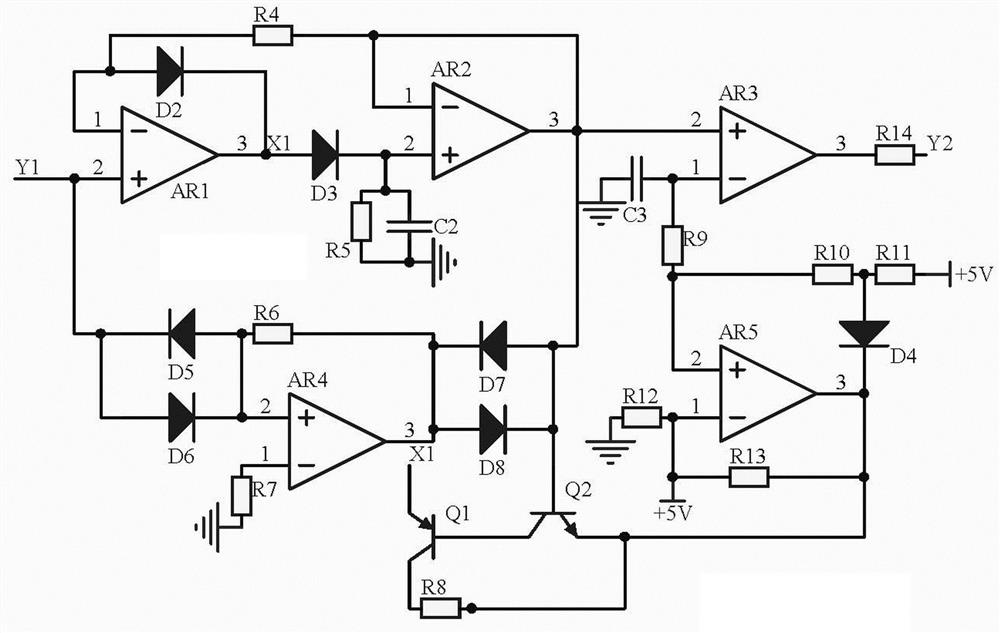
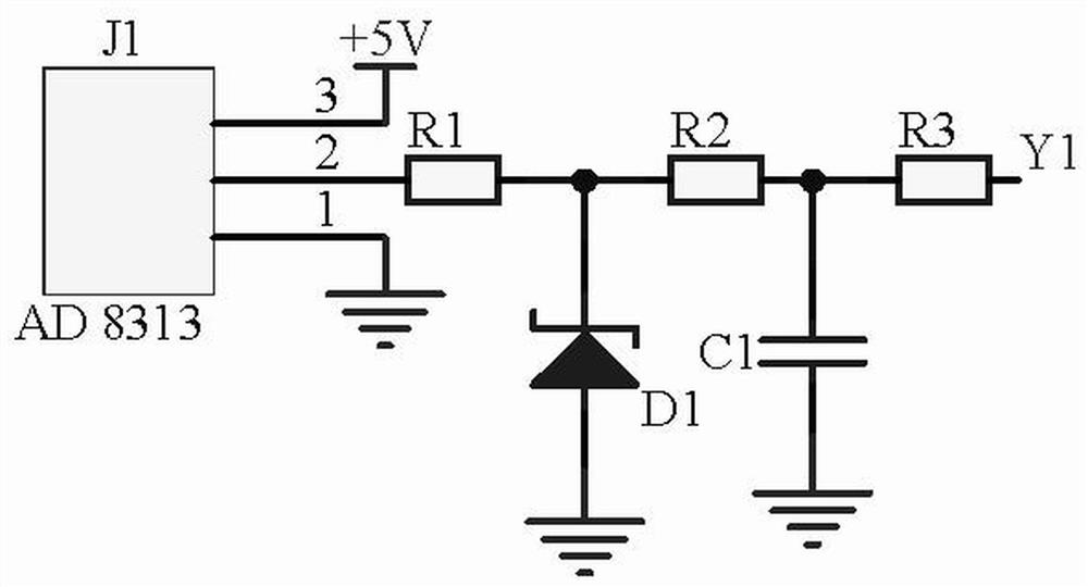
[0012] Embodiment 1, an optical cable signal transmission system, including a waveform detection module, a limiting pulse width module and a limiting transmission module, the waveform detection module uses the AD 8313 detector J1 to collect the signal waveform when the optical cable transmitting end is working , the limiting pulse width module is divided into two ways to receive the output signal of the waveform detection module, the first way uses the op amp AR1, the op amp AR2 and the diode D2, and the diode D3 to form a peak screening circuit to screen out the peak signal, and the second way uses Diode D5-diode D8 and operational amplifier AR4 form a limiting circuit to deepen the signal pulse width limiting depth, and the two signals are input together into the pulse width expansion circuit composed of operational amplifier AR3, operational amplifier AR5 and capacitor C3, and use a triode Q1 and transistor Q2 further detect the amplitude difference between the two signals, ...

Embodiment 2

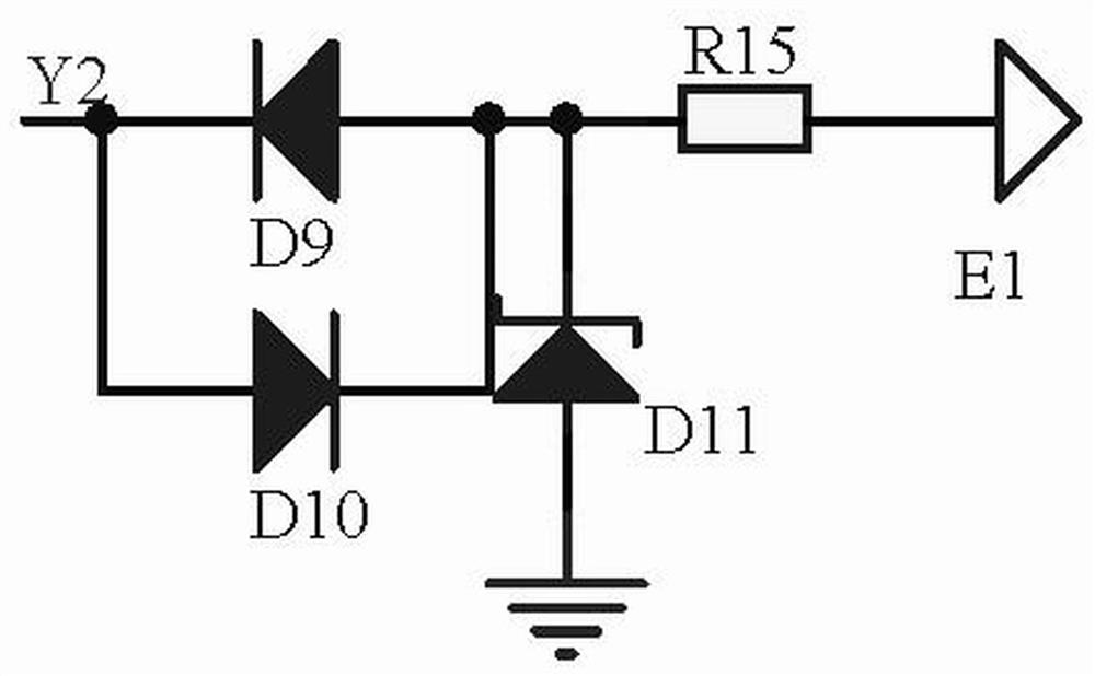
[0015] Embodiment 2. On the basis of Embodiment 1, the limiting transmission module uses diode D9 and diode D10 to form a limiting circuit to limit the signal, and send it to the optical cable signal controller through the signal transmitter E1, which is the optical cable signal control. The error reference signal of the device, the cathode of the diode D9 is connected to the anode of the diode D10 and the other end of the resistor R14, the anode of the diode D9 is connected to the cathode of the diode D10, one end of the resistor R15 and the cathode of the regulator D11, and the anode of the regulator D11 Ground, the other end of the resistor R15 is connected to the signal transmitter E1;

[0016] The waveform detection module selects the detector J1 model of AD 8313 to collect the signal waveform when the optical cable emitter is working, the power supply terminal of the detector J1 is connected to the power supply +5V, the ground terminal of the detector J1 is grounded, and ...


PUM


Abstract

The invention discloses an optical cable signal transmission system. The device comprises a waveform detection module, an amplitude limiting pulse width module and an amplitude limiting transmitting module, the waveform detection module uses a detector J1 with a model of AD 8313 to acquire a signal waveform when an optical cable emitting end works. The amplitude limiting pulse width module receives signals output by the waveform detection module in two paths; in one path, an operational amplifier AR1, an operational amplifier AR2, a diode D2 and a diode D3 form a peak value screening circuit to screen out a peak value signal; in the second path, diodes D5-D8 and an operational amplifier AR4 are used to form an amplitude limiting circuit to deepen the signal pulse width amplitude limiting depth; the two paths of signals are input into a pulse width expanding circuit consisting of an operational amplifier AR3, an operational amplifier AR5 and a capacitor C3; and finally, the amplitude limiting transmitting module uses a diode D9 and a diode D10 to form an amplitude limiting circuit to limit the amplitude of the signal, and the signal is transmitted into the optical cable signal controller through the signal transmitter E1, so that the signal waveform can be calibrated when the optical cable transmitting end works, and is converted into an error reference signal of the optical cable signal controller.

Description

technical field [0001] The invention relates to the technical field of signal transmission, in particular to an optical cable signal transmission system. Background technique [0002] At present, the optical cable signal transmission system replaces the carrier transmission step by step in the power grid, and new problems have also arisen in the optical signal transmission. Although the transmission efficiency is fast and the anti-interference ability is strong, it is also prone to distortion, resulting in signal pulse width. Small, the amplitude is too large, and then the signal received by the optical cable signal controller loses data, reducing the stability of the optical cable signal transmission system. Contents of the invention [0003] In view of the above situation, in order to overcome the defects of the prior art, the purpose of the present invention is to provide an optical cable signal transmission system, which can calibrate the signal waveform when the optic...

Claims


Application Information

Patent Timeline
Patent Type & Authority Patents(China)
IPC IPC(8): H04B10/25
Inventor 李韬
Owner CHINA TELECOM CONSTR 3RD ENG
Learn More