
IGBT driving overcurrent protection and short-circuit protection system circuit

A technology of over-current protection circuit and short-circuit protection circuit, which is applied to emergency protection circuit devices, electrical components, output power conversion devices, etc. It can solve the problems of high protection discrimination voltage, short duration of blind zone, long duration of blind zone, etc., and achieve reliable Effect of overcurrent and short circuit protection

Active Publication Date: 2020-06-12
霍煜
View PDF13 Cites 0 Cited by
  • Summary
  • Abstract
  • Description
  • Claims
  • Application Information

AI Technical Summary

Problems solved by technology

[0005] The short circuit is the direct behavior of the power supply voltage in the IGBT. Usually, the upper and lower IGBTs in the half-bridge system are turned on at the same time, or the output of the full bridge or the three-phase bridge is passed through. The working characteristic of the IGBT at this time is that the IGBT is turned on When the current increases rapidly, the VCE voltage increases rapidly. At this time, the protection discrimination voltage is higher and the blind zone duration is shorter.
The overcurrent behavior means that when the output is short-circuited, there is a certain reactance at the output or the cable is long, or the system is out of control. At this time, the working characteristics of the IGBT are: the output current rises slowly, and the VCE voltage rises low. At this time, the protection time The discrimination voltage is low, and the duration of the blind zone is long;

Method used


Image

  • IGBT driving overcurrent protection and short-circuit protection system circuit
  • IGBT driving overcurrent protection and short-circuit protection system circuit
  • IGBT driving overcurrent protection and short-circuit protection system circuit

Examples


Embodiment Construction

[0029] The technical solutions in the embodiments of the present invention will be clearly and completely described below in conjunction with the accompanying drawings in the embodiments of the present invention. Apparently, the described embodiments are only some, not all, embodiments of the present invention. Based on the embodiments of the present invention, all other embodiments obtained by persons of ordinary skill in the art without making creative efforts belong to the protection scope of the present invention.

[0030] see Figure 1 to Figure 5 , the present invention provides a technical solution:

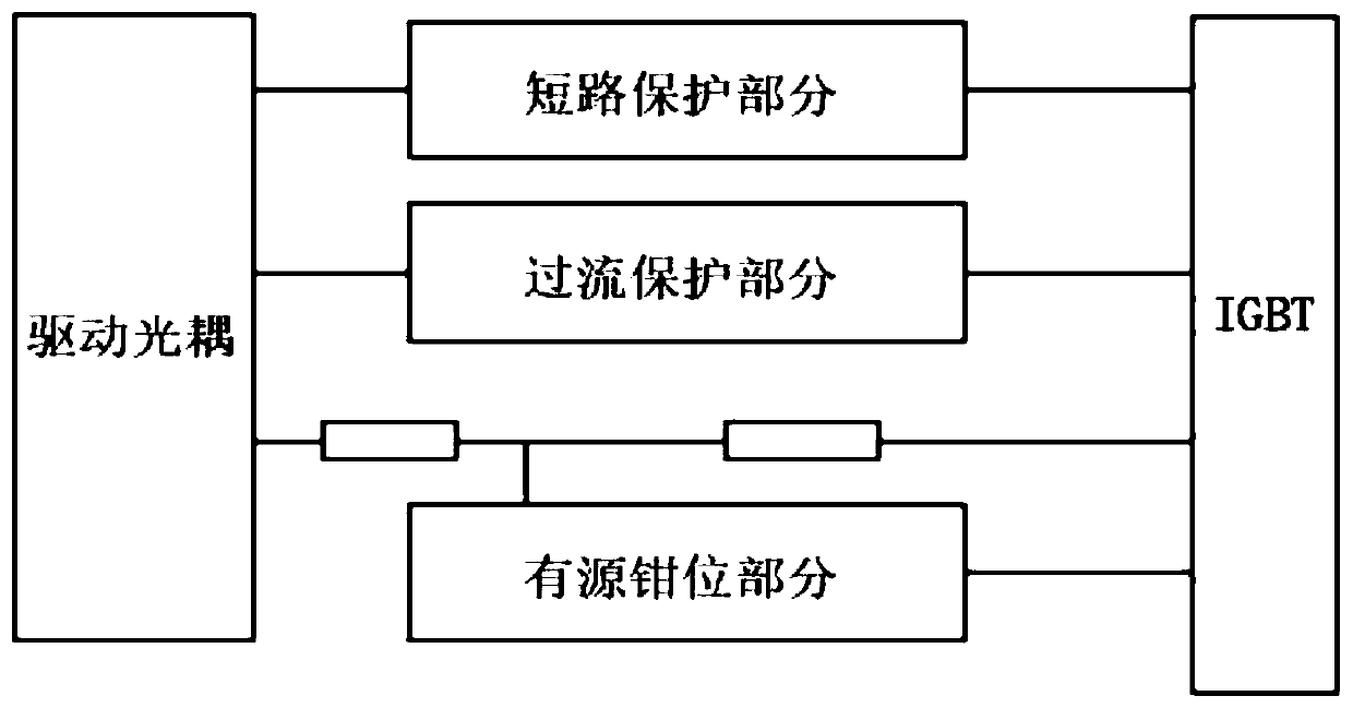
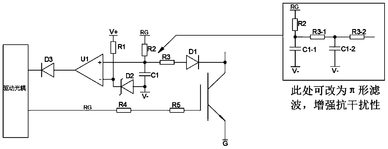
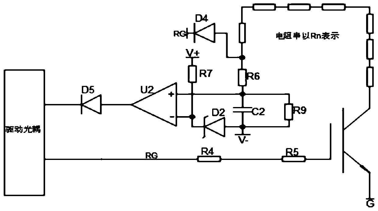
[0031] IGBT drive overcurrent protection and short circuit protection system circuit, including drive optocoupler, overcurrent protection circuit, short circuit protection circuit and active clamping circuit, the overcurrent protection circuit, short circuit protection circuit and active clamping circuit can be independently When combined, a better IGBT protection effect ...


PUM


Abstract

The invention discloses an IGBT drive overcurrent protection and short circuit protection system circuit. The circuit comprises a drive optocoupler, an overcurrent protection circuit, a short-circuitprotection circuit and an active clamping circuit, wherein the over-current protection circuit, the short-circuit protection circuit and the active clamping circuit can be used independently. A betterIGBT protection effect is achieved during combination. The drive optocoupler, the overcurrent protection circuit, the short-circuit protection circuit and the active clamping circuit are in drive connection with the IGBT, the overcurrent protection circuit can independently send overcurrent protection signals, and the short-circuit protection circuit can independently send short-circuit protection signals. According to the circuit system, the IGBT can be effectively protected; reliable over-current and short-circuit protection is achieved, dead zone timing is conducted in an RC mode, anti-interference processing is conducted through pi-type connection when necessary, when the comparator detects that the voltage on RC reaches the set voltage, output of the comparator is turned over, abnormal signals are sent out, detection is conducted through the control optocoupler, wave sealing is conducted, and the IGBT is turned off to achieve the purpose of protection.

Description

technical field [0001] The invention relates to the technical field of electronic device protection, in particular to an IGBT drive overcurrent protection and short circuit protection system circuit. Background technique [0002] IGBT has good characteristics such as easy driving, high withstand voltage, large current, high speed and low saturation voltage drop, so it has been widely used, such as widely used in inverters, SVG, high-power power supplies, motor adjustment, soft start and Inverter welding machines and other equipment. [0003] IGBT is the same as other electronic devices. In addition to the device performance it can provide, the practicability also depends on the circuit conditions and switching environment. Therefore, how to drive and protect the IGBT to ensure the safe and reliable operation of the IGBT is the key to the design of the IGBT drive circuit. difficulties and key points. [0004] In actual practice, due to the obvious difference between the per...

Claims


Application Information

Patent Timeline
Patent Type & Authority Applications(China)
IPC IPC(8): H02H7/12H02M1/32
CPCH02H7/1203H02M1/32
Inventor 霍煜
Owner 霍煜
Learn More