Phosphating treatment device for split pin

A processing device and phosphating pool technology, which is applied in the coating process of metal materials, etc., can solve problems such as inconsistent concentration, influence on enterprise production, and uneven phosphating, so as to prevent uneven concentration, facilitate placement and collection, and improve phosphorus concentration. The effect of chemical efficiency

Inactive Publication Date: 2020-06-12
宜昌市恒昌标准件有限责任公司
View PDF0 Cites 0 Cited by
  • Summary
  • Abstract
  • Description
  • Claims
  • Application Information

AI Technical Summary

Problems solved by technology

During the processing of cotter pins, surface phosphating is required for anti-corrosion after the forming is completed, and because the cotter pin workpieces are small, it is difficult to collect and salvage them directly in the phosphating pool, and the accumulation of workpieces will also affect the phosphating quality of the workpieces and efficiency
In order to keep the phosphating temperature constant, the existing phosphating device adopts the method of adding hot water to increase the liquid temperature when the temperature of the phosphating solution is low, but this will reduce the concentration of the phosphating solution and affect the production of the enterprise. The phosphating solution is static, and the concentration is inconsistent during the phosphating process, resulting in uneven phosphating

Method used


Image

  • Phosphating treatment device for split pin
  • Phosphating treatment device for split pin

Examples


Embodiment Construction

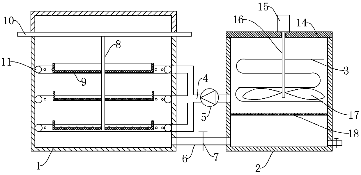
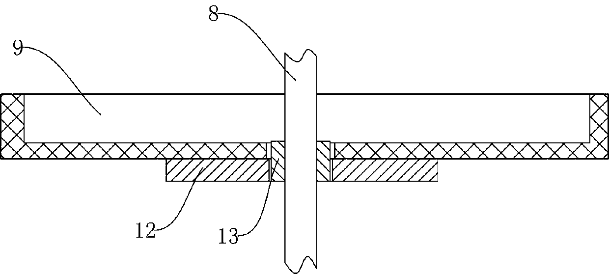
[0010] Such as figure 1 As shown, a cotter pin phosphating treatment device includes a phosphating tank 1 and a liquid storage tank 2, a heating coil 3 is arranged in the liquid storage tank 2, a sewage outlet is provided at the bottom, a valve is provided on the sewage outlet, and the liquid storage tank 2 communicate with the phosphating tank 1 through the liquid inlet pipe 4, the liquid inlet pipe 4 is provided with a water pump 5, the bottom of the phosphating tank 1 is connected with the liquid storage tank 2 through the liquid return pipe 6, and the liquid return pipe 6 is provided with a valve 7, A storage rack is provided in the phosphating tank 1, and the storage rack includes a support rod 8 and several layers of storage boxes 9 arranged on the support rod 8. The storage box 9 is a screen structure, and the storage box 9 is arranged along the height of the support rod 8. The upper end of the support rod 8 is provided with a limiting plate 10 , and the limiting plate ...


PUM


Abstract

The invention provides a phosphating treatment device for a split pin. The phosphating treatment device comprises a phosphating tank and a liquid storage tank, wherein a drive motor is arranged on anupper cover of the liquid storage tank; the output end of the drive motor is connected to a stirring shaft in the liquid storage tank; a stirring blade is arranged on the stirring shaft; the inner wall of the liquid storage tank is provided with a heating coiled tube; the liquid storage tank communicates with the phosphating tank through a liquid inlet tube; a water pump is arranged on the liquidinlet tube; spraying tubes which communicate with the liquid inlet tube are arranged in the phosphating tank; the multiple spraying tubes are arranged along the height of the phosphating tank; the bottom of the phosphating tank communicates with the liquid storage tank through a liquid return tube; a valve is arranged on the liquid return valve; a filter screen is arranged in the liquid storage tank; a storage rack is arranged in the phosphating tank; the storage rack comprises a supporting rod and a plurality of layers of storage boxes; supporting plates are arranged at the lower sides of thestorage boxes; a connecting barrel is arranged on a supporting rod; the supporting plates are connected to the connecting barrel through threads; the upper end of the supporting rod is provided witha limiting plate; and the limiting plate supports the upper side of the phosphating tank. The device can perform uniform phosphating on the split pin, improves phosphating efficiency, and facilitatesplacing and collecting of workpieces.

Description

technical field [0001] The invention belongs to the field of cotter pin processing equipment, and in particular relates to a cotter pin phosphating treatment device. Background technique [0002] Phosphating is a commonly used metal surface treatment technology. Phosphating is a process in which a chemical or electrochemical reaction forms a phosphate chemical conversion film. The formed phosphate conversion film is called a phosphating film. The purpose of phosphating is mainly to provide protection for the base metal and prevent the metal from being corroded to a certain extent. frictional lubrication. During the processing of cotter pins, surface phosphating is required for anti-corrosion after the forming is completed, and because the cotter pin workpieces are small, it is difficult to collect and salvage them directly in the phosphating pool, and the accumulation of workpieces will also affect the phosphating quality of the workpieces and efficiency. In order to keep...

Claims


Application Information

Patent Timeline
Patent Type & Authority Applications(China)
IPC IPC(8): C23C22/00
CPCC23C22/00
Inventor 朱艺
Owner 宜昌市恒昌标准件有限责任公司
Why Eureka
Try Eureka