
Self-rescue winch suitable for industrial vehicle

A technology for industrial vehicles and winches, applied in the field of self-rescue winches, can solve the problems of increasing production costs, troubles, and inability to travel, and achieve the effects of improving the scope of application, simple positioning effect, and improving use effect.

Pending Publication Date: 2020-06-12
ANHUI HELI CO LTD
View PDF0 Cites 0 Cited by
  • Summary
  • Abstract
  • Description
  • Claims
  • Application Information

AI Technical Summary

Problems solved by technology

In road construction or mining areas in remote mountainous areas in the south, the roads are often muddy due to rain, the road surface is uneven, and the counterweight of industrial vehicles is placed at the rear, and the front-wheel drive is particularly easy to get stuck in the mud when it is empty and cannot drive. Sometimes it can only be pushed or pulled by a car, and the rescue cannot be carried out smoothly with a car
Only four-wheel-drive off-road vehicles or engineering vehicles can be used for on-site rescue, which is very troublesome. The solution in the prior art is to configure a winch on the wheel hub, and has the following technical defects:
[0003] 1: The vehicle’s self-rescue function is realized by driving the winch to wind the rope through the rotation of the wheel, while only one end of the traditional winch is fixed on the wheel hub, which cannot realize the structural size design for vehicles of different tonnages, and cannot achieve sufficient connection strength and rescue traction: ;
[0004] 2: The end of the twisted rope is fixed on the car body during the traction process of the traditional winch. Once the wheels slip or the force direction is unstable, it will cause structural damage to the car body;
[0005] 3: The traditional winch is a single solid cylinder structure, which cannot achieve lightweight structure and increases the production cost of the enterprise

Method used


Image

  • Self-rescue winch suitable for industrial vehicle
  • Self-rescue winch suitable for industrial vehicle
  • Self-rescue winch suitable for industrial vehicle

Examples


Embodiment Construction

[0025] The present invention will be further described below in conjunction with accompanying drawing:

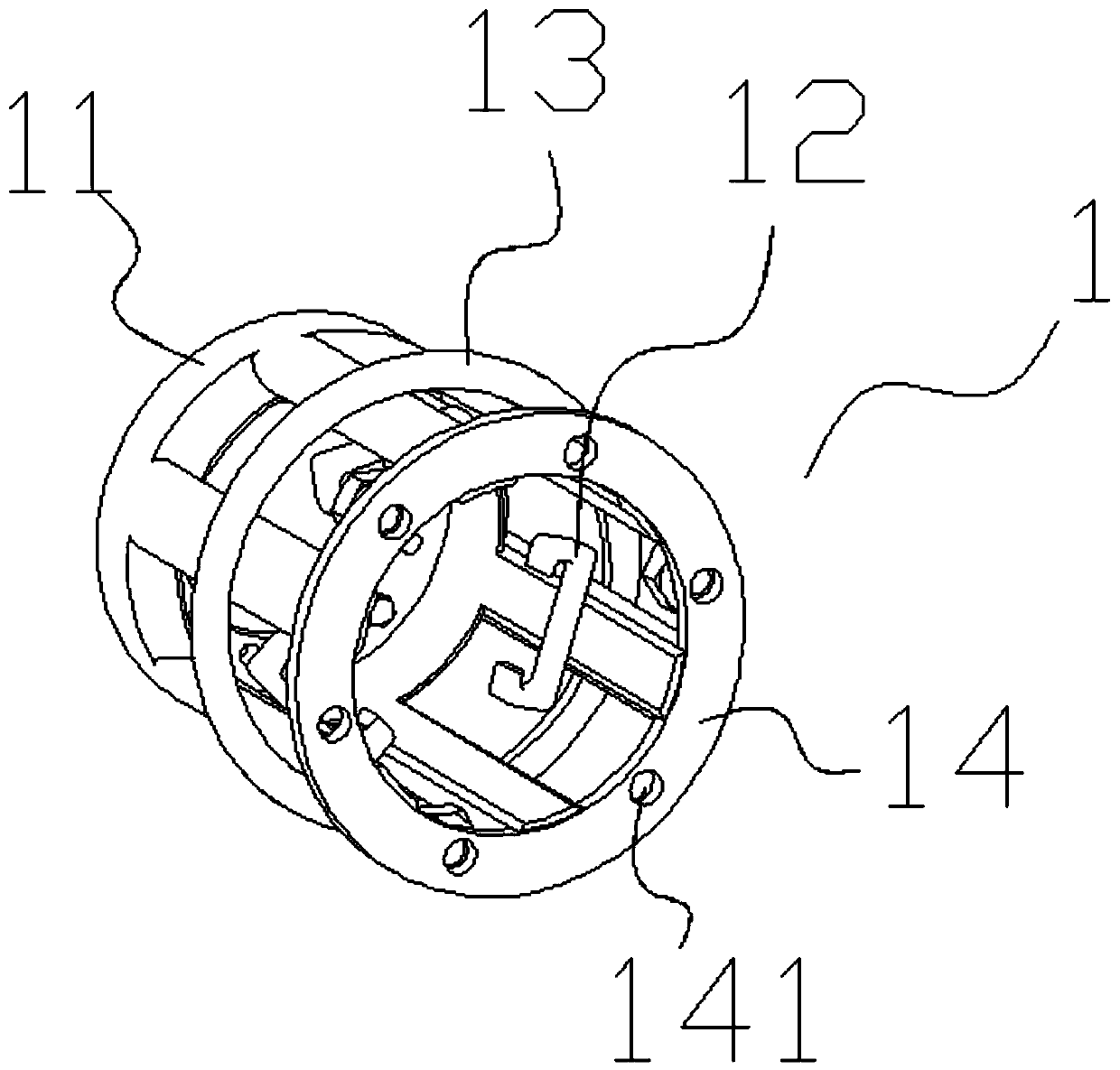
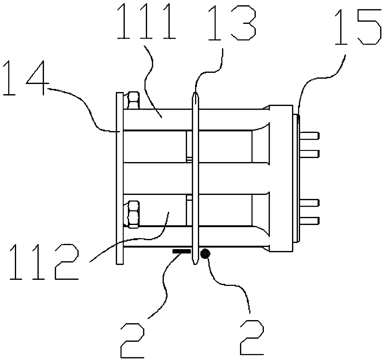
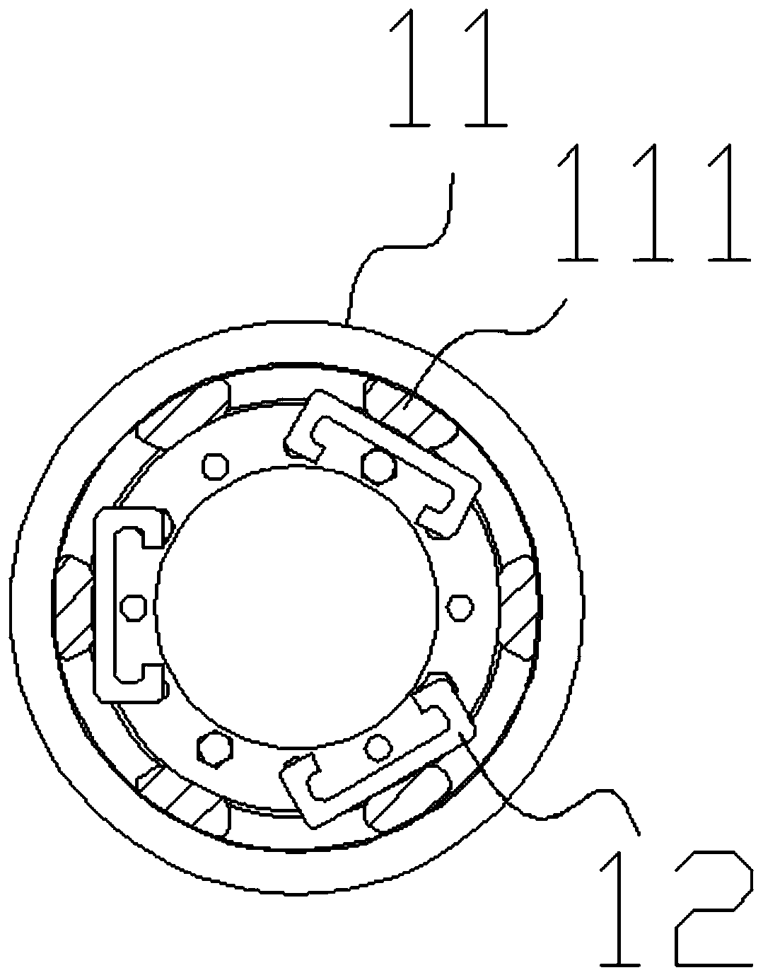
[0026] like Figure 1-7 A self-rescue winch suitable for industrial vehicles is shown, the self-rescue winch is installed at the axial end face of the vehicle hub 3, and the end face of the wheel hub 3 includes a hub installation disk surface 31 and a wheel hub installation disk surface 31 end surface. The half-shaft end cover 32, this kind of self-rescue winch makes the winch body 1 have the function of selectively assembling on the end face of the hub mounting plate 31 or the end face of the half-shaft end cover 32 by adopting a two-way assembly scheme, and at the same time combines the winch body 1 The structural optimization realizes the functions of light weight and easy hooking of the winch. The specific structure is as follows:

[0027] The self-rescue winch includes a winch body 1, one end of the winch body 1 is provided with an assembly surface 14 for being fixedl...


PUM


Abstract

The invention discloses a self-rescue winch suitable for an industrial vehicle. The self-rescue winch is installed on the axial end face of a hub of the vehicle, the end face of the hub comprises a hub installation disc face and a half shaft end cover arranged on the end face of the hub installation disc face, the self-rescue winch comprises a winch body, one end of the winch body is provided witha first assembly surface used for being fixedly connected to the hub installation disc face, the other end of the winch body is provided with a second assembly surface used for being fixedly connected to the half shaft end cover, a cage body frame is composed of a plurality of supporting ribs arranged in the axial direction of the winch body, and at least one special-shaped hook is arranged on the inner ring portion of each supporting rib. According to the self-rescue winch, the winch with the cage body frame structure is adopted, the lightweight design of the winch is achieved, meanwhile, the application range of the winch is further widened through the combination with the double-head structure design of the winch, and a guide ring can effectively prevent a twisted rope from interferingwith tires or hubs, so that the using effect of the winch is improved.

Description

technical field [0001] The invention relates to the technical field of vehicle winches, in particular to a self-rescue winch suitable for industrial vehicles. Background technique [0002] Among industrial vehicles, there are many special vehicles used to carry goods, such as forklifts, and such vehicles are more and more widely used in practice. There are currently some area-specific limitations for industrial vehicles. In road construction or mining areas in remote mountainous areas in the south, the roads are often muddy due to rain, the road surface is uneven, and the counterweight of industrial vehicles is placed at the rear, and the front-wheel drive is particularly easy to get stuck in the mud when it is empty and cannot drive. Sometimes it can only be pushed or pulled by a car, and the rescue cannot be carried out smoothly with a car. Only four-wheel-drive off-road vehicles or engineering vehicles can be used for on-site rescue, which is very troublesome. The solut...

Claims


Application Information

Patent Timeline
Patent Type & Authority Applications(China)
IPC IPC(8): B66D1/74B66D1/36
CPCB66D1/7442B66D1/36
Inventor 陈国友翟道理常方坡
Owner ANHUI HELI CO LTD
Learn More