
Front anti-collision beam, frame and automobile with same

A technology of front anti-collision beams and vehicle frames, applied in the direction of bumpers, etc., can solve the problems of increasing energy absorption effect, small force on the upper and lower plates, and large force on the middle plate, so as to improve the deformation resistance and energy absorption capacity , easy to extrude and bend into shape, saving layout space

Active Publication Date: 2013-07-24
GREAT WALL MOTOR CO LTD
View PDF5 Cites 7 Cited by
  • Summary
  • Abstract
  • Description
  • Claims
  • Application Information

AI Technical Summary

Problems solved by technology

[0002] The thicknesses of the horizontal upper plate, middle plate and lower plate in the front anti-collision beam of traditional vehicles are not equal to each other, which brings inconvenience to the bending process, specifically, during the bending process, the thickness of the middle plate is greater than that of the upper plate and lower plate When the thickness is high, the force on the middle plate is relatively large, and the force on the upper and lower plates is small, and the processing is easy to lose stability. Moreover, although increasing the thickness of the middle plate can increase the energy absorption effect, it increases the weight of the front anti-collision beam, thus making it lighter. Insufficient Quantitative Design
In addition, the traditional cross-sectional structure of the front anti-collision beam is relatively regular, which is not conducive to the shape design and layout space design of the vehicle front

Method used


Image

  • Front anti-collision beam, frame and automobile with same
  • Front anti-collision beam, frame and automobile with same
  • Front anti-collision beam, frame and automobile with same

Examples


Embodiment Construction

[0025] Embodiments of the present invention are described in detail below, examples of which are shown in the drawings, wherein the same or similar reference numerals designate the same or similar elements or elements having the same or similar functions throughout. The embodiments described below by referring to the figures are exemplary only for explaining the present invention and should not be construed as limiting the present invention.

[0026] In describing the present invention, it is to be understood that the terms "center", "upper", "lower", "front", "rear", "left", "right", "vertical", "horizontal", The orientations or positional relationships indicated by "top", "bottom", "inner", "outer", etc. are based on the orientations or positional relationships shown in the drawings, and are only for the convenience of describing the present invention and simplifying the description, rather than indicating or implying References to devices or elements must have a particular ...


PUM


Abstract

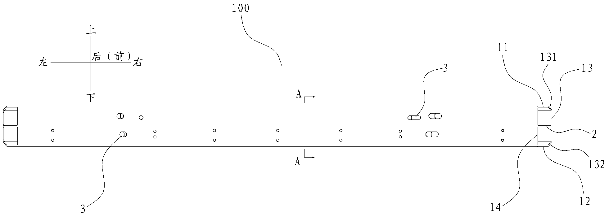
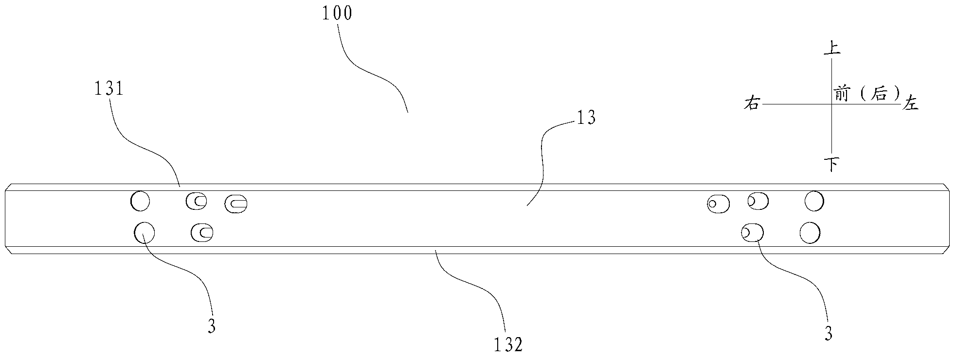
The invention discloses a front anti-collision beam, a frame and an automobile with the front anti-collision beam and the frame. The front anti-collision beam comprises a body. The body comprises an upper plate, a lower plate, a first lateral plate, a second lateral plate and a middle plate, wherein the lower plate is arranged below the upper plate; the first lateral plate is connected between the front end of the first lateral plate and the front end of the second lateral plate, the second lateral plate is connected between the rear end of the first lateral plate and the rear end of the second lateral plate, the middle plate is arranged between the upper plate and the lower plate and is respectively connected with the first lateral plate and the second lateral plate, and the thickness of the middle plate, the thickness of the upper plate and the thickness of the lower plate are almost the same. According to the front anti-collision beam, because the upper plate, the middle plate and the lower plate are designed to be of the same-thickness structure, the front anti-collision beam is easier formed by extrusion in a bending mode, and a lightweight design is achieved under the premise that the requirements for collision energy absorption are met.

Description

technical field [0001] The invention relates to the field of automobiles, in particular to a front anti-collision beam, a vehicle frame and an automobile with the same. Background technique [0002] The thicknesses of the horizontal upper plate, middle plate and lower plate in the front anti-collision beam of traditional vehicles are not equal to each other, which brings inconvenience to the bending process, specifically, during the bending process, the thickness of the middle plate is greater than that of the upper plate and lower plate When the thickness is high, the force on the middle plate is relatively large, and the force on the upper and lower plates is small, and the processing is easy to lose stability. Moreover, although increasing the thickness of the middle plate can increase the energy absorption effect, it increases the weight of the front anti-collision beam, thus making it lighter. Insufficient quantitative design. In addition, the traditional cross-section...

Claims


Application Information

Patent Timeline
Patent Type & Authority Applications(China)
IPC IPC(8): B60R19/02
Inventor 黄勇徐波王志明王学军李勇君宋红双毛磊
Owner GREAT WALL MOTOR CO LTD
Learn More