Semi-automatic water path cleaning device for photovoltaic power station assembly

A technology for cleaning devices and photovoltaic power plants, applied in photovoltaic power generation, photovoltaic modules, electrical components, etc., can solve the problems of difficult cleaning, component surface wear, and high cleaning costs, achieve a high degree of intelligence, prevent excessive movement, and have a good cleaning effect. Effect

Pending Publication Date: 2020-06-12
中新春兴新能源电力(苏州)有限公司
View PDF0 Cites 0 Cited by
  • Summary
  • Abstract
  • Description
  • Claims
  • Application Information

AI Technical Summary

Problems solved by technology

[0003] Photovoltaic modules have been in harsh weather conditions in the wild for a long time, and the dust accumulated on the surface of photovoltaic modules is generally not cleaned in time, forming dirt and difficult to clean
In particular, the west of my country is dry and rainless, and there are many sandy and dusty weathers. A large amount of sand and dust deposited on the surface of photovoltaic modules greatly blocks and weakens the penetration of sunlight. Decrease in power generation efficiency of components
[0004] At present, various forms of cleaning methods have been introduced at home and abroad, such as manual and mechanical cleaning. Manual cleaning is labor-intensive, while the photovoltaic module cleaning vehicle uses a car-tonned water tank, and a large wiper is installed on the side, and the wiper is sprayed on the surface of the module for cleaning. The surface of the component is cleaned by using a huge wiper arm under human control, which consumes a lot of secondary energy, and because the wiper carries muddy water on the surface of the component during the cleaning process, it is easy to cause surface wear of the component, and due to the volume of the vehicle-mounted component cleaning vehicle It can only be limited to the application of large-scale and plain ground power stations, the application is limited, and the cleaning cost is very high

Method used


Image

  • Semi-automatic water path cleaning device for photovoltaic power station assembly

Examples


Embodiment Construction

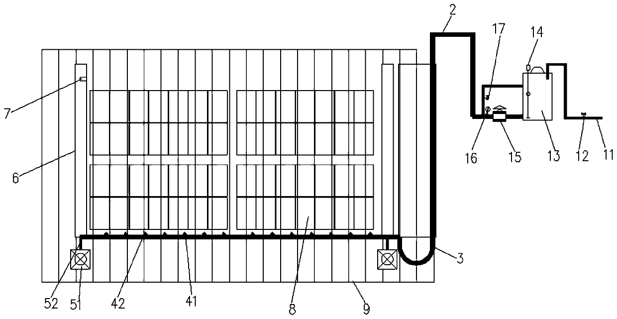
[0028] Firstly, the original design intention of the present invention is explained, because the labor intensity of manual cleaning of photovoltaic modules is high at present, and the photovoltaic module cleaning vehicle adopts a car-tonned water tank, and a large wiper is installed on the side, and the wiper is sprayed on the surface of the module to clean the surface of the module. Using huge wiper arms to clean the surface of components under human control consumes a lot of secondary energy, and because the wiper carries muddy water on the surface of the components during the cleaning process, it is easy to cause surface wear of components, and because the vehicle-mounted component cleaning vehicle is large in size, it can only be limited For large-scale, plain ground power stations, the application is limited, and the cleaning cost is very high. In order to make the cleaning device more convenient for cleaning photovoltaic modules and make it more suitable for the current ma...


PUM


Abstract

The invention discloses a semi-automatic water path cleaning device for a photovoltaic power station assembly. The semi-automatic water path cleaning device comprises an electrical control box which controls each electrical component, and a PLC module which connects and controls between each component is arranged in the electrical control box; and the semi-automatic water path cleaning device further comprises a water supply device connected with the electrical control box to supply water, a first water inlet pipe connected with the water supply device to make water in the water supply deviceto flow out, a connecting pipe connected with the first water inlet pipe to transfer the water, a cleaning assembly connected with the connecting pipe to clean the photovoltaic power station assembly,and a moving assembly connected with the cleaning assembly to control the movement of the cleaning assembly, so as to clean the photovoltaic power station assembly comprehensively. The semi-automaticwater path cleaning device has the beneficial effects that through the matching of the water supply device, the connecting pipe, the first water inlet pipe, the cleaning assembly and the moving assembly, the photovoltaic power station assembly can be effectively cleaned from top to bottom, the cleaning effect is good, the method is simple, and the semi-automatic water path cleaning device is convenient for people to use.

Description

technical field [0001] The invention relates to the technical field of photovoltaic power station component cleaning, in particular to a semi-automatic waterway cleaning device for photovoltaic power station components. Background technique [0002] At present, solar power is used in many areas of our country, and photovoltaics are needed for solar energy collection and power generation, and the amount of photovoltaic power generation mainly depends on the number of photovoltaic modules, efficiency of photovoltaic modules, transmission loss of inverter efficiency, solar radiation, and environment Impact and Operations Management. The surface pollution of photovoltaic modules is the main reason for affecting the power generation. The surface pollution of photovoltaic modules will block the light reaching the photovoltaic modules and affect the heat dissipation. In addition, the dust with acid and alkali deposits on the surface of photovoltaic modules, which will corrode the b...

Claims


Application Information

Patent Timeline
Patent Type & Authority Applications(China)
IPC IPC(8): B08B3/02B08B13/00H02S40/10
CPCB08B3/02B08B13/00H02S40/10Y02E10/50
Inventor 李景涛
Owner 中新春兴新能源电力(苏州)有限公司
Why Eureka
Try Eureka