A burner for a gas stove
A technology for burners and gas stoves, which is applied to gas fuel burners, burners, and incombustible liquid/gas transportation, etc., can solve the problems of insufficient residence time of flue gas at the bottom of the pot, waste of resources, low efficiency, etc. The effect of solving the shortage of secondary air supplement, improving combustion efficiency and improving thermal efficiency
- Summary
- Abstract
- Description
- Claims
- Application Information
AI Technical Summary
Problems solved by technology
Method used
Image
Examples
Embodiment 1
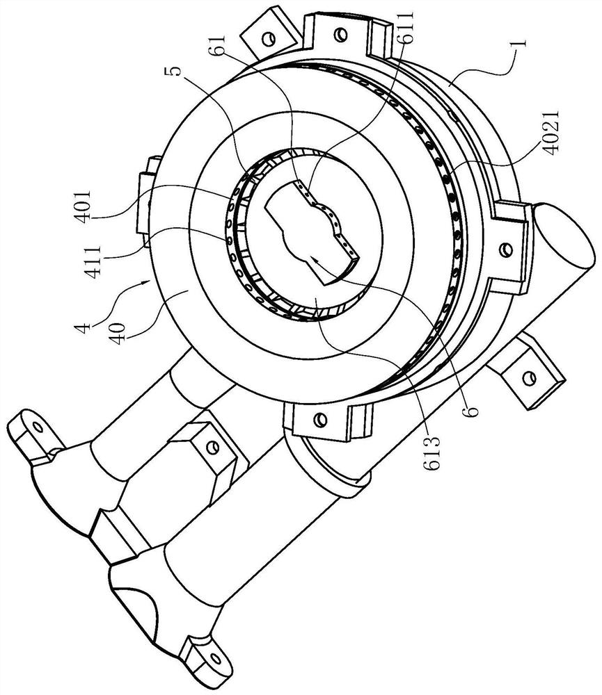
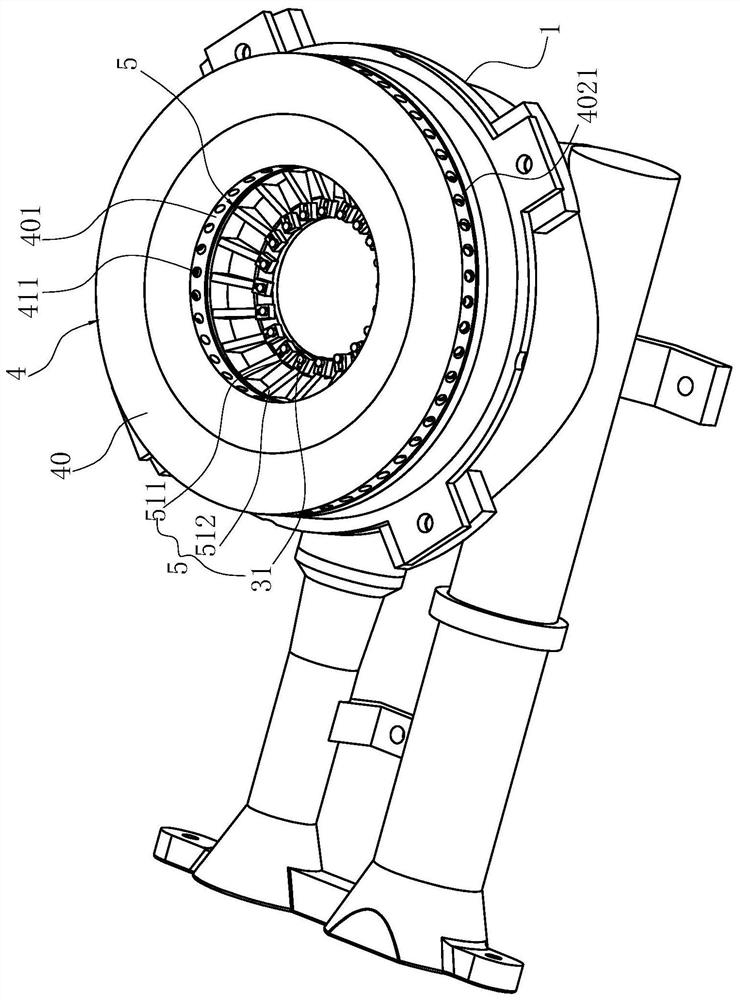
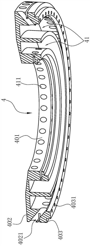
[0040] like Figure 1-9Shown is the preferred embodiment of the present invention. The burner used in the gas stove in this embodiment includes a base 1, the base 1 has an inner wall 11 and an outer wall 12 arranged at intervals inside and outside, the inner wall 11 surrounds a central cavity 111 for replenishing gas, the inner wall 11 and the outer wall 12 jointly surround a peripheral cavity 121; the connecting body 2 includes a plate body, the central position of the plate body has a central hole 21 aligned with the central cavity 111, and the periphery of the central hole 21 has a vertical inner ring The wall 221 forms the annular cavity 3 around the central hole 21, the outer periphery of the plate extends in the horizontal direction and can cover the outer wall 12, and the outer periphery has a vertical outer annular wall 220 and at least forms with the inner annular wall 221 Annular gas channel 22, the gas channel 22 is in communication with the peripheral cavity 121; ...
Embodiment 2
[0045] The structure is basically the same as that of Embodiment 1, the only difference is that: each deflector 5 also has the function of storing overflow liquid, and each deflector 5 partially has a concave-convex structure 513 between the root 511 and the free end 512, like Figure 10 shown.
Embodiment 3
[0047] The structure is basically the same as that of Embodiment 1, the only difference is that the liquid guiding element enters the air outlet 1111 of the central cavity 111 in a sliding manner, and the flow guiding element 5 can at least partially enter the central cavity 111 along the radial direction. The air outlet 1111 reduces the secondary air entering each inner fire hole 411 by blocking the air outlet 1111, as Figure 11 shown.
PUM
 Abstract
Description
Claims
Application Information
 - R&D Engineer
- R&D Manager
- IP Professional
- Industry Leading Data Capabilities
- Powerful AI technology
- Patent DNA Extraction
Browse by: Latest US Patents, China's latest patents, Technical Efficacy Thesaurus, Application Domain, Technology Topic, Popular Technical Reports.
© 2024 PatSnap. All rights reserved.Legal|Privacy policy|Modern Slavery Act Transparency Statement|Sitemap|About US| Contact US: help@patsnap.com


