Embedding structure and method for improving pavement cracking around luminous floor tile

A technology for floor tiles and pavement, which is applied in the field of improving the buried structure of pavement cracks around luminous floor tiles, achieving the effects of being easy to replace, reducing construction and maintenance costs, and facilitating construction

Active Publication Date: 2020-06-09
NANTONG UNIVERSITY
View PDF8 Cites 5 Cited by
  • Summary
  • Abstract
  • Description
  • Claims
  • Application Information

AI Technical Summary

Problems solved by technology

[0004] The purpose of the present invention is to provide a buried structure and method for improving the cracking of the road surface around the luminous floor tiles. The structure can be freely expanded and contracted along the laying direction of the floor tiles and perpendicular to the laying direction of the floor tiles. It is firm and reliable, and the vehicle runs smoothly without jumping and noise. , The expansion joints can prevent rainwater and garbage from seeping and blocking. The expansion device has a reliable waterproof and drainage system, which is easy to install and maintain. It can effectively solve the problems of cracks, potholes, subsidence, looseness and rutting on the surrounding road surface during the laying of luminous floor tiles. and other diseases, to solve the problems raised in the above-mentioned background technology

Method used


Image

  • Embedding structure and method for improving pavement cracking around luminous floor tile
  • Embedding structure and method for improving pavement cracking around luminous floor tile
  • Embedding structure and method for improving pavement cracking around luminous floor tile

Examples


Embodiment Construction

[0045] The following will clearly and completely describe the technical solutions in the embodiments of the present invention with reference to the accompanying drawings in the embodiments of the present invention. Obviously, the described embodiments are only some, not all, embodiments of the present invention. Based on the embodiments of the present invention, all other embodiments obtained by persons of ordinary skill in the art without making creative efforts belong to the protection scope of the present invention.

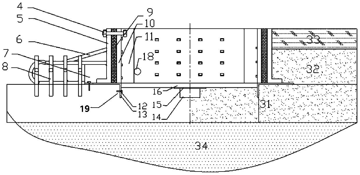
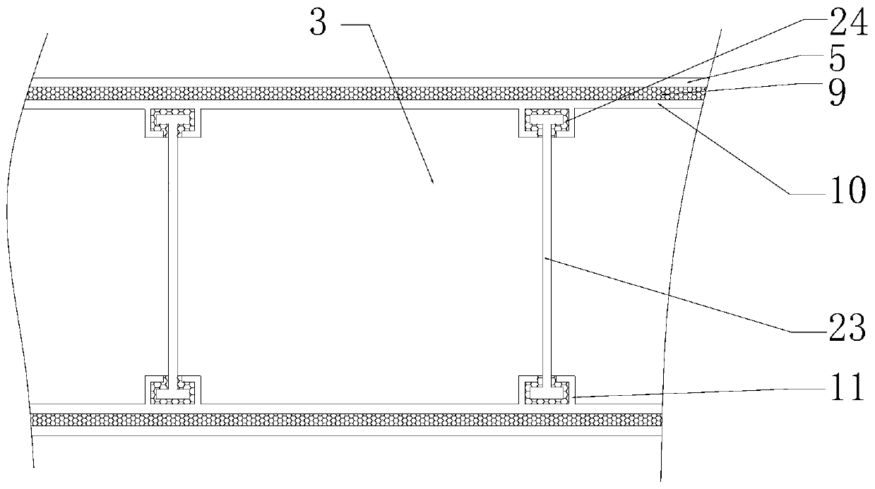
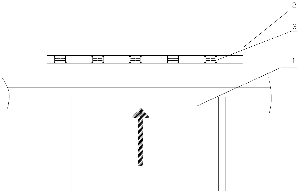
[0046] see Figure 1 to Figure 7 , the present invention provides a technical solution: a buried structure for improving cracking of the road surface around the luminous floor tiles, including a driveway 1, a road surface groove 2, a luminous floor tile 3, a fixing bolt 4, an anchor plate 5, an anchor rib 6, and an anchor rib connecting plate 7. Steel bar 8, expansion joint rubber strip 9, special-shaped steel 10, partition installation groove 11, angle steel bo...


PUM


Abstract

The invention discloses an embedding structure and method for improving pavement cracking around a luminous floor tile. A pavement groove is embedded above a pavement, the luminous floor tile is arranged above the pavement groove, the pavement groove is dug between a zebra crossing and a carriageway, a base concrete layer is arranged at the upper part in the pavement groove, angle steel is arranged in an angle steel mounting groove through an angle steel bolt, reinforcing steel bars are arranged on one side above the base concrete layer, a drainage groove is formed at the middle above the baseconcrete layer, an anchoring plate and deformed steel are vertically arranged above the angle steel, an expansion joint rubber strip is arranged between the anchoring plate and the deformed steel, ananchoring rib is connected to the reinforcing steel bars in a welded mode, a bottom plate is arranged at the bottom of the deformed steel, both ends of partition plates are arranged in partition plate installation grooves through installation groove rubber strips, the luminous floor tile is arranged on a floor tile supporting plate, a second concrete layer is arranged on the base concrete layer,and an asphalt surface layer is arranged on the second concrete layer. The problem of water accumulation at the bottom of a cast iron box of an existing pavement light-emitting device can be solved, the pavement telescopic effect is solved, and damage of brake starting to the pavement is reduced.

Description

technical field [0001] The invention relates to the technical field of transportation facilities, in particular to an embedding structure and method for improving cracking of road surfaces around luminous floor tiles. Background technique [0002] The zebra crossing is the life safety line of pedestrians. Due to the inability to provide early warning, especially the "low-headed people" who have weak awareness of prevention when crossing the road, traffic accidents on the zebra crossing are not uncommon. In response to this phenomenon, some technology companies cooperated with universities to develop luminous floor tiles, which effectively reduced the accident rate at traffic intersections. The two columns "Into Science" and "The Road to Ingenuity" made special reports on this. [0003] The pavement cases and on-site investigations of the existing pavement luminous devices found that the original pavement buried with luminous floor tiles is prone to large cracks or even crack...

Claims


Application Information

Patent Timeline
Patent Type & Authority Applications(China)
IPC IPC(8): E01C17/00E01C5/00E01C11/22E01C23/04E01F9/582
CPCE01C5/003E01C11/225E01C17/00E01C23/04E01F9/582
Inventor 徐勋倩王建波施卫东徐海黎沈标周井玲项宏亮杨霄杨威顾钰雯付尚静
Owner NANTONG UNIVERSITY
Why Eureka
Try Eureka