Crystallizer for copper alloy electromagnetic continuous casting

A copper alloy and mold technology, which is applied in the field of molds for electromagnetic continuous casting of copper alloys, can solve the problems of low production efficiency, surface defects, large grain size, etc. Internal quality, overcoming the effect of large grain size

Pending Publication Date: 2020-06-09
DALIAN UNIV OF TECH +1
View PDF0 Cites 3 Cited by
  • Summary
  • Abstract
  • Description
  • Claims
  • Application Information

AI Technical Summary

Problems solved by technology

However, from the perspective of meeting actual production needs, the molds for electromagnetic continuous casting in the prior art still have the following deficiencies: 1. It is difficult to achieve the unity of good electromagnetic penetration, wear resistance and safety for the mold cylinder; 2. The structure of the cooling water jacket is difficult to achieve the unity of uniform cooling, secondary cooling and compact structure of the cooling water jacket; 3. It is difficult to achieve the unity of firmness, durability and convenient assembly as a whole; the above deficiencies directly affect the surface and internal quality of the slab, continuous casting The billet is prone to surface defects, the grain size is large, macro segregation is formed, the overall performance of the product is not good, the yield is not high, the production efficiency is not high and the production cost is increased

Method used


Image

  • Crystallizer for copper alloy electromagnetic continuous casting
  • Crystallizer for copper alloy electromagnetic continuous casting
  • Crystallizer for copper alloy electromagnetic continuous casting

Examples


Embodiment Construction

[0026] The specific embodiments of the present invention will be further described below in conjunction with the accompanying drawings. What needs to be declared here is that the descriptions of these embodiments are used to help understand the present invention, but are not intended to limit the present invention. In addition, the technical features involved in the various embodiments of the present invention described below may be combined with each other as long as they do not conflict with each other.

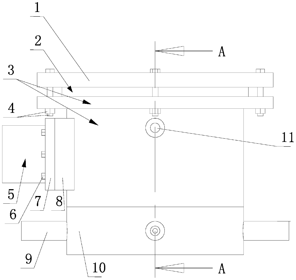
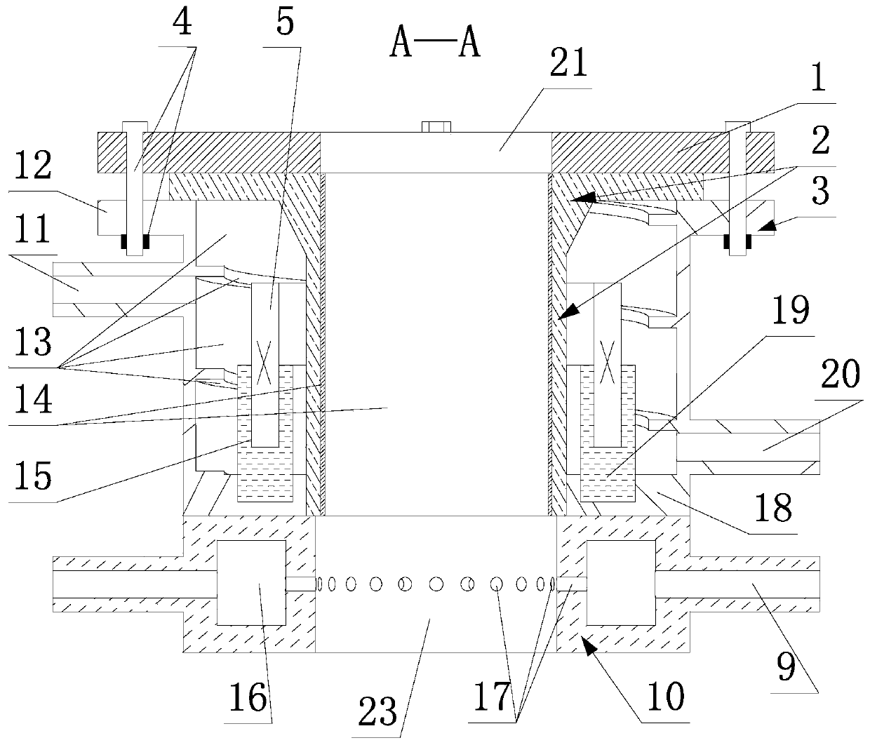
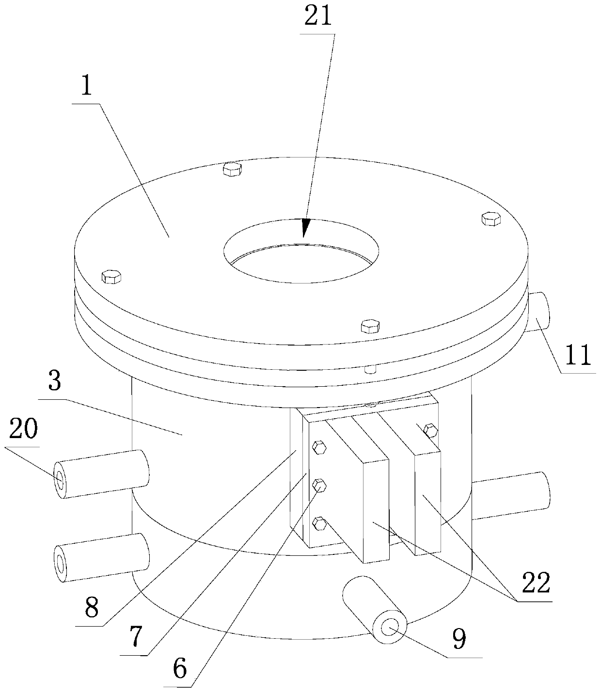
[0027] Such as figure 1 , figure 2 , image 3 , Figure 4 , Figure 5 , Figure 6 , Figure 7 , Figure 8 , Figure 9 shown

[0028]The copper alloy electromagnetic continuous casting crystallizer of the present invention comprises a copper alloy liquid inlet, a copper alloy accommodating cavity, a copper ingot outlet, an upper cover 1, a slotted crystallizer cylinder body 2, a first cooling water jacket 3 and a first cooling water jacket fixed on the first The e...


PUM

PropertyMeasurementUnit
Thicknessaaaaaaaaaa

Abstract

The invention discloses a crystallizer for copper alloy electromagnetic continuous casting. According to the crystallizer, an upper cover, a seamed crystallizer cylinder an a first cooling water jacket are fixed into a sealed body. The first cooling water jacket is provided with wiring windows allowing two terminals of an electromagnetic coil to extend out of a wall to be externally connected witha power source. The seam of the seamed crystallizer cylinder is filled with a insulated material and sealant which can transmit electromagnetism. A first graphite sleeve is fixed to the inner wall ofthe seamed crystallizer cylinder. A water cavity of the first cooling water jacket is a vertical spiral water channel. The lower part of the outer wall of the first cooling water jacket is provided with a first water inlet. The upper part of the outer wall of the first cooling water sleeve is provided with a first water outlet. The crystallizer for copper alloy electromagnetic continuous castingfurther comprises a second cooling water jacket fixed to the bottom of the first cooling water jacket. A center hole of the upper cover, an inner hole of the graphite sleeve and a center hole of the second cooling water jacket are located on the same axis and form a copper alloy melt inlet, a copper alloy containing cavity and a copper ingot outlet from top to bottom. The crystallizer cylinder hasstrong electromagnetism transmitting capacity and is resistant to wear, good in safety and good in cooling effect, and the structure of the cooling water jackets is compact.

Description

technical field [0001] The invention relates to the technical field of copper alloy preparation, in particular to a crystallizer for electromagnetic continuous casting of copper alloy. Background technique [0002] With the rapid development of my country's industrial technology, the demand for copper and copper alloys is also increasing. The electromagnetic continuous casting technology can purify the melt, improve the segregation of copper alloy elements, improve the surface quality of the slab, refine the grains, and improve the mechanical properties of the slab. The mold is the most critical equipment or component in the electromagnetic continuous casting technology. [0003] There are many kinds of crystallizers for electromagnetic continuous casting in the prior art, with different structures. However, from the perspective of meeting actual production needs, the molds for electromagnetic continuous casting in the prior art still have the following deficiencies: 1. It ...

Claims


Application Information

Patent Timeline
IPC IPC(8): B22D11/049B22D11/055
CPCB22D11/004B22D11/049B22D11/055
Inventor 亚斌冯斌张兴国葛小牛周秉文黄敏孟令刚冯茜群
Owner DALIAN UNIV OF TECH
Why Eureka
Try Eureka