
A chassis dynamometer motor frame with torque detection and radial cooling functions

A chassis dynamometer, radial cooling technology, applied in the direction of electromechanical devices, electrical components, electric components, etc., can solve problems such as vibration and temperature measurement and control difficulties, abnormal output data of torque detection devices, and restrictions on motor design and application. , to achieve the effect of improving convenience and installation efficiency, reasonable structure and convenient operation

Active Publication Date: 2020-12-11
REGAL BELOIT WUXI
View PDF4 Cites 0 Cited by
  • Summary
  • Abstract
  • Description
  • Claims
  • Application Information

AI Technical Summary

Problems solved by technology

Therefore, there are certain difficulties in the measurement and control of the vibration and temperature of the chassis dynamometer motor, especially for large-scale chassis dynamometer motors. The detection platform is connected to the torque detection device. The position change will cause the output data of the torque detection device to be abnormal, and the real data cannot be obtained
The conventional design scheme in this field has no radial air duct structure, the stator core is directly connected to the enclosure, and the heat dissipation mainly depends on the forced heat dissipation on the surface, so the heat dissipation performance is not good, and the normal operation of the motor can only be ensured by increasing the core and coil materials and reducing the power density
At the same time, the detection platform is simply welded on the hoarding plate, and the deformation reduction of the relative position can only be controlled by increasing the thickness of the hoarding plate
And the installation method in which the entire motor is suspended on the overall equipment of the dynamometer through the shaft has certain requirements on the weight and volume of the motor, which limits the design and application of the motor

Method used


Image

  • A chassis dynamometer motor frame with torque detection and radial cooling functions
  • A chassis dynamometer motor frame with torque detection and radial cooling functions
  • A chassis dynamometer motor frame with torque detection and radial cooling functions

Examples


Embodiment Construction

[0032] The specific implementation manner of the present invention will be described below in conjunction with the accompanying drawings.

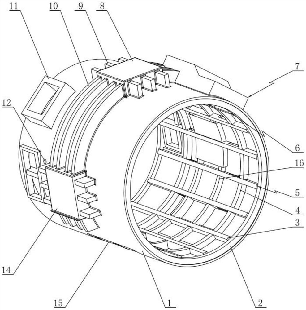
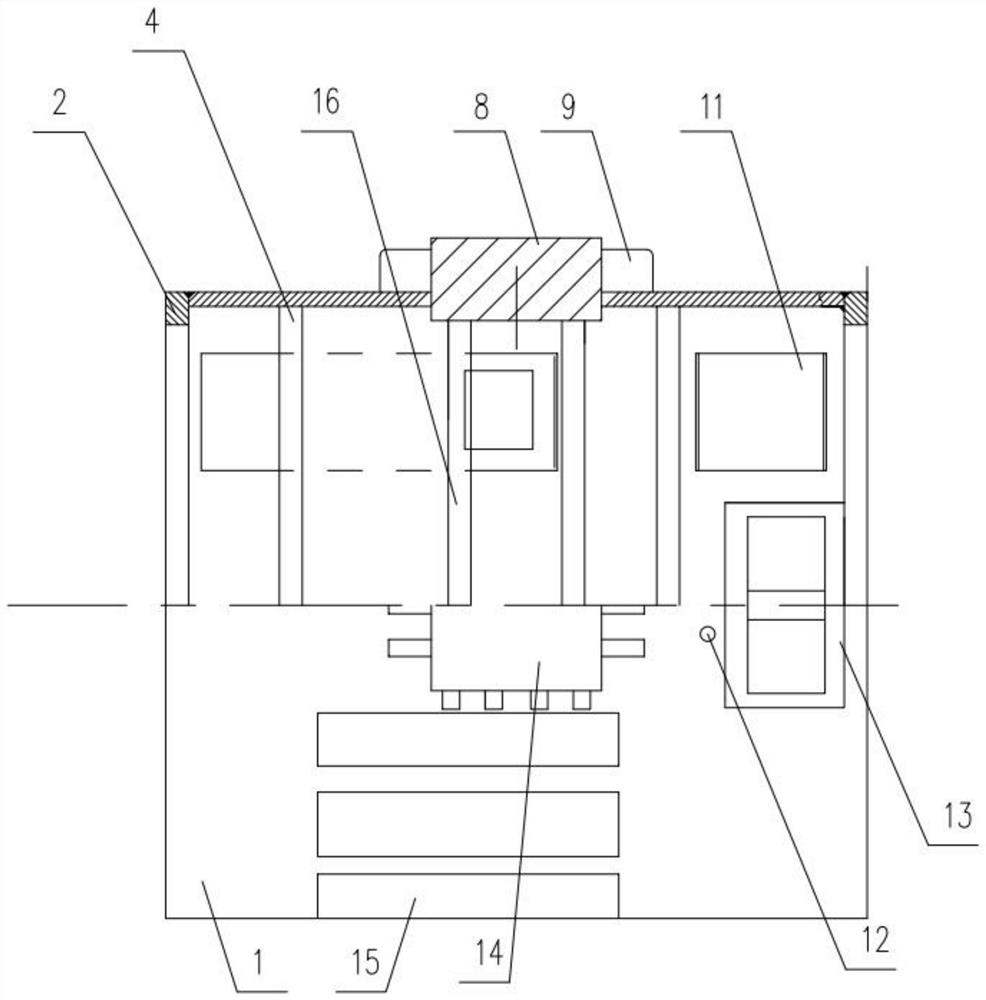
[0033] Such as Figure 1~2 As shown, the present invention includes a coaming plate, and the two side edges of the coaming plate are bent toward each other and abut against each other, so that the coaming plate is closed to form a base body 1, which is a cylindrical hollow body; the middle part of the outer wall of the base body 1 is Several detection platform mounting holes are opened equidistantly, and the vertical detection platform 8 and the horizontal detection platform 14 are respectively arranged in the detection platform mounting holes, and the outer circumference of the vertical detection platform 8 and the horizontal detection platform 14 are also fixedly connected with the outer wall strengthening mechanism, in a group The first air inlet mechanism is arranged between the adjacent detection platform mounting holes, and several a...


PUM


Abstract

The invention discloses a chassis dynamometer motor base with torque detection and radial cooling functions. The chassis dynamometer motor base comprises a motor base main body; a vertical detection platform and a horizontal detection platform which are fixedly connected with an outer wall reinforcing mechanism are respectively arranged in the middle of the outer wall of the motor base main body;the chassis dynamometer motor base further comprises a first air inlet mechanism, a second air inlet mechanism, a wiring port and a grounding point; and the inner wall of the motor base main body isprovided with a reticular reinforcing structure which is formed by fixedly connecting a first end plate, a second end plate, a reinforcing rib plate and internal axial reinforcing ribs in a crossed manner. According to the invention, by arranging the inner and outer reinforcing ribs, the structural strength is improved; a detection platform is directly reinforced; the weights of the external reinforcing ribs and the internal reinforcing ribs are far less than the weight of the thickened motor base main body due to the same effect; ventilation grooves are formed in part of the internal axial reinforcing ribs, so that the heat dissipation performance is improved; cooling is facilitated through cooperation of the first air inlet device, the second air inlet device and the gap between the reinforcing rib plate and the motor base main body; and the overall power density of the motor is greatly improved.

Description

technical field [0001] The invention relates to the technical field of motor bases, in particular to a chassis dynamometer motor base with functions of torque detection and radial cooling. Background technique [0002] The standard GB755 has clear regulations on the vibration and temperature rise limits of rotating motors, but there is no corresponding regulation on chassis dynamometer motors. Therefore, there are certain difficulties in the measurement and control of the vibration and temperature of the chassis dynamometer motor, especially for large-scale chassis dynamometer motors. The detection platform is connected to the torque detection device. The position change will cause the output data of the torque detection device to be abnormal, and the real data cannot be obtained. The conventional design scheme in this field has no radial air passage structure, the stator core is directly connected to the shroud, and the heat dissipation mainly depends on the forced heat di...

Claims


Application Information

Patent Timeline
Patent Type & Authority Patents(China)
IPC IPC(8): H02K5/00H02K5/20H02K11/20H02K11/24H02K5/22
CPCH02K5/00H02K5/20H02K5/225H02K11/20H02K11/24
Inventor 王皓周传华徐建国
Owner REGAL BELOIT WUXI
Learn More