
Resistance-type power divider and manufacturing process thereof

A power divider and resistive technology, which is applied in the direction of circuits, electrical components, waveguide devices, etc., can solve the problems of limiting the application range of resistive power dividers, insertion loss and VSWR key performance deterioration, etc., to achieve The effect of expanding the use of frequency bands, small circuit size, and high graphics accuracy

Pending Publication Date: 2020-06-05
NO 43 INST OF CHINA ELECTRONICS TECH GRP CETC
View PDF0 Cites 1 Cited by
  • Summary
  • Abstract
  • Description
  • Claims
  • Application Information

AI Technical Summary

Problems solved by technology

But in the higher frequency band (12~18GHz), due to the parasitic capacitance effect of the resistor, the key performances of the existing resistive power divider, such as insertion loss and voltage standing wave ratio, will be obviously deteriorated, which seriously limits the resistive power The scope of application of the dispenser

Method used


Image

  • Resistance-type power divider and manufacturing process thereof
  • Resistance-type power divider and manufacturing process thereof

Examples


Embodiment Construction

[0027] In order to facilitate understanding of the present invention, the present invention will be described more fully below in conjunction with specific embodiments. However, the present invention can be embodied in many different forms and is not limited to the embodiments described herein. On the contrary, the purpose of providing these embodiments is to make the disclosure of the present invention more thorough and comprehensive.

[0028] Unless otherwise defined, all technical and scientific terms used herein have the same meaning as commonly understood by one of ordinary skill in the technical field of the invention. The terminology used herein in the description of the present invention is only for the purpose of describing specific embodiments, and is not intended to limit the present invention.

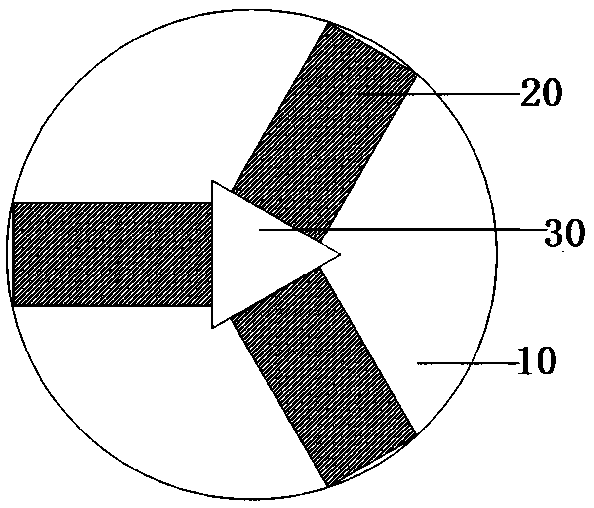
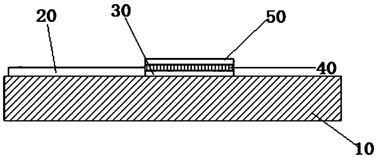
[0029] see figure 1 , this embodiment discloses a resistive power divider, which includes a substrate 10 , a microstrip layer 20 , a resistive layer 30 , a dielectric lay...


PUM

PropertyMeasurementUnit
Thicknessaaaaaaaaaa
Square resistanceaaaaaaaaaa
Thicknessaaaaaaaaaa

Abstract

The invention discloses a resistance-type power divider and a manufacturing process thereof. The resistance-type power divider comprises a substrate, a resistance layer which is arranged on the surface of the substrate and located in the middle of the substrate, and a microstrip layer which is arranged on the surface of the substrate. A dielectric layer and an electrode layer are sequentially arranged on the resistance layer. The use frequency band range of the power divider is expanded by adopting a composite structure of multiple layers of films.

Description

technical field [0001] The invention belongs to the field of power dividers, and in particular relates to a resistive power divider and a manufacturing process thereof. Background technique [0002] A power divider is a device that divides one input signal energy into two or more outputs with equal or unequal energy. It belongs to passive microwave devices and is mainly used for power distribution or power synthesis. In microwave equipment such as phased array radars and multi-channel relay communication machines, power dividers are more and more widely used, and users have higher and higher requirements for the performance of power dividers. The general performance requirements are: wide frequency band, small insertion loss, small voltage standing wave ratio, high power withstand, high isolation between ports, good amplitude and phase consistency between output ports, simple circuit form, small size, etc. [0003] The common Wilkinson power dividers on the market are mostl...

Claims


Application Information

Patent Timeline
IPC IPC(8): H01P5/12H01P11/00
CPCH01P5/12H01P11/00
Inventor 刘牛车江波夏寅徐浩然吴波
Owner NO 43 INST OF CHINA ELECTRONICS TECH GRP CETC
Learn More