Fingerprint identification electronic equipment

A technology for fingerprint identification and electronic equipment, applied in the field of communication, can solve the problems of uneven brightness and darkness in the display area of ​​liquid crystal display devices, and achieve the effects of maintaining luminous brightness and uniformity, reducing losses, and accurate and effective collection

Pending Publication Date: 2020-06-05
SHENZHEN LONGLI TECH CO LTD
View PDF3 Cites 1 Cited by
  • Summary
  • Abstract
  • Description
  • Claims
  • Application Information

AI Technical Summary

Problems solved by technology

In addition, when the fingerprint identification unit 110 is placed above the backlight device, from the viewing angle of the display screen, the light transmittance of the display area where the fingerprint identification unit is placed below is compared to the light transmittance of other display areas where the fingerprint identification unit is not provided. It should be low, and the LED backlight at the bottom provides a uniform plane light source. The display area where the fingerprint recognition unit is set below is darker than other areas, and the display area of ​​the liquid crystal display device is unevenly bright and dark.

Method used


Image

  • Fingerprint identification electronic equipment
  • Fingerprint identification electronic equipment
  • Fingerprint identification electronic equipment

Examples


Embodiment 1

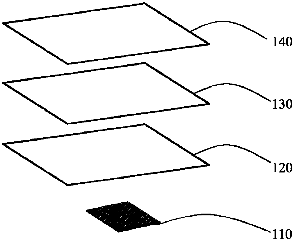
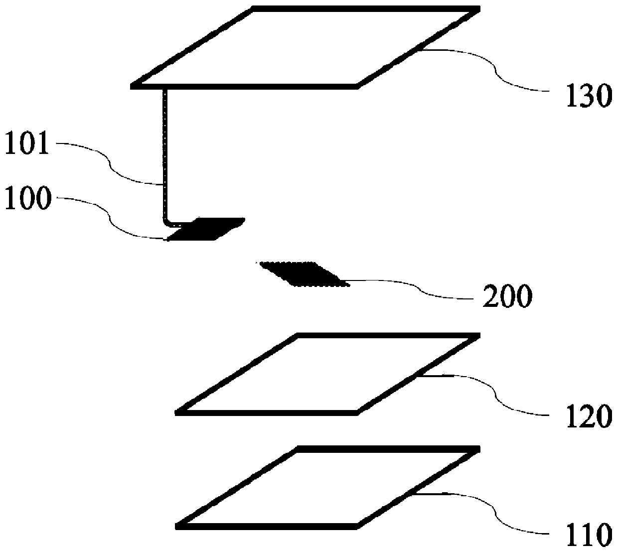
[0027] First, through Figure 2-3 , the electronic device for fingerprint recognition according to Embodiment 1 of the present invention will be described, which includes a glass cover plate 130, an LCD liquid crystal panel 120, and a backlight module 110 that are sequentially stacked from top to bottom; a fingerprint recognition sensor 100 and The infrared light emitter 100 is integrally arranged on the side of the glass cover plate 130; and the infrared reflective film 200 is arranged between the glass cover plate 130 and the LCD liquid crystal panel 120; wherein, the infrared reflective film 200 is transparent in the visible light region, It is used to reflect the infrared light signal transmitted through the glass cover 130 to the fingerprint identification sensor.

[0028] In the electronic device used for fingerprint recognition in this embodiment, through the setting of the infrared reflective film 200, the infrared reflective film 200 effectively transmits the infrared...

Embodiment 2

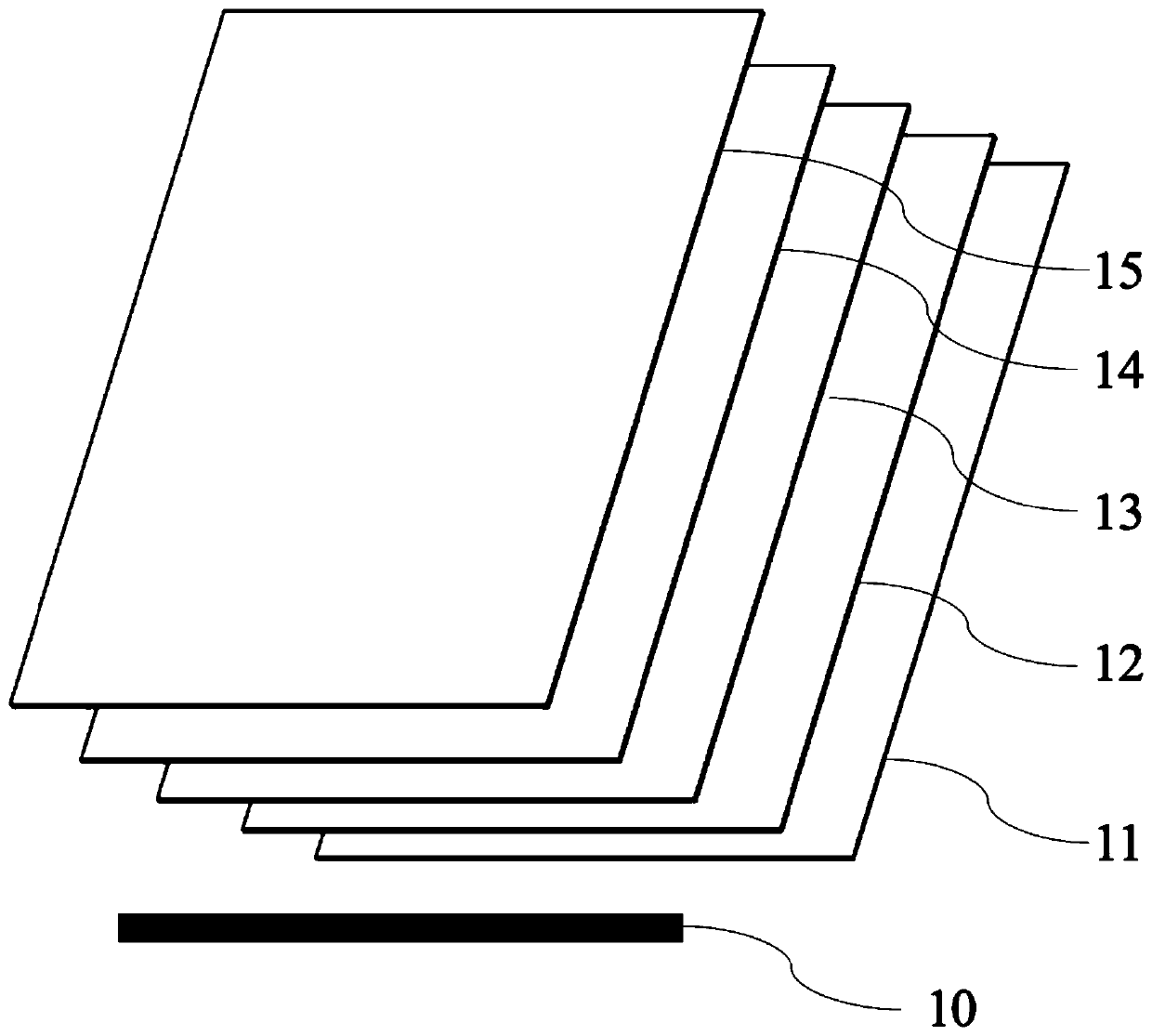
[0033] Please refer to Figure 4, is an exploded view of the backlight module of the fingerprint identification terminal device according to Embodiment 2 of the present invention. Only the differences between Embodiment 2 and Embodiment 1 will be described below, and the similarities will not be repeated here.

[0034] The fingerprint recognition sensor 100 and the infrared light emitter 110 are disposed separately on the side of the glass cover 130 . The size of the infrared reflective film 200 corresponds to the size of the glass cover 130 .

Embodiment 3

[0036] Please refer to Figure 5 , is an exploded view of the backlight module of the fingerprint identification terminal device according to Embodiment 3 of the present invention. Only the differences between Embodiment 3 and Embodiment 2 will be described below, and the similarities will not be repeated here.

[0037] The infrared reflective film 200 is disposed between the glass cover 130 and the LCD liquid crystal panel.

[0038] Example 3

[0039] Please refer to Image 6 , is an exploded view of the backlight module of the fingerprint identification terminal device according to Embodiment 3 of the present invention. Only the differences between Embodiment 3 and Embodiment 2 will be described below, and the similarities will not be repeated here.

[0040] The infrared light emitter 110 is arranged under the fingerprint identification sensor 100, and there is no shield between the two.


PUM

PropertyMeasurementUnit
wavelengthaaaaaaaaaa
refractive indexaaaaaaaaaa

Abstract

The invention discloses fingerprint identification electronic equipment. The fingerprint identification electronic equipment comprises a glass cover plate, an LCD liquid crystal panel and a backlightmodule which are sequentially laminated from top to bottom, a fingerprint identification sensor and an infrared light emitter are arranged on a side surface of the glass cover plate; an infrared reflecting film is arranged between the glass cover plate and the backlight module; wherein the infrared reflecting film is transparent in a visible light area and is used for reflecting an infrared lightsignal penetrating the glass cover plate to the fingerprint identification sensor. The fingerprint identification electronic equipment can enable a fingerprint identification signal to be effectivelytransmitted on fingerprint identification terminal equipment and accurately acquire biological fingerprint information, and does not influence the display image quality of an LCD display screen at thesame time.

Description

technical field [0001] The invention relates to the technical field of communication, in particular to an electronic device for fingerprint recognition in an LCD screen. Background technique [0002] Fingerprint sensing and matching is a reliable and widely used technology. A common method of fingerprint identification involves scanning a sample fingerprint or an image thereof and storing the image and / or unique characteristics of the fingerprint image, the characteristics of the sample fingerprint can be compared with information from reference fingerprints already present in a database to determine the correct identification of the user , for example for verification purposes. In particular, in-display fingerprint recognition is currently becoming more and more popular due to its ease of operation and versatility, and its suitability for compact portable electronic devices. [0003] The fingerprint recognition display device in the LCD screen obviously has a larger range...

Claims


Application Information

Patent Timeline
Patent Type & Authority Applications(China)
IPC IPC(8): G06K9/00G06K9/20G02B5/08G02F1/1333G02F1/13357G02B6/00
CPCG02B5/08G02F1/1333G02F1/133606G02B6/0043G02B6/0058G02F1/133607G06V40/1324G06V10/145
Inventor 张小齐刘政彭益曾晓虎
Owner SHENZHEN LONGLI TECH CO LTD
Why Eureka
Try Eureka