Antenna model load displacement measurement method of mixed basis function

An antenna model, load displacement technology, applied in CAD numerical modeling, design optimization/simulation, etc., can solve problems such as inaccuracy, deviation, neglect of support structure deformation, etc., to improve accuracy, achieve accurate measurement, and avoid parameter mapping Effect

Inactive Publication Date: 2020-06-05
ZHEJIANG UNIV
View PDF5 Cites 0 Cited by
  • Summary
  • Abstract
  • Description
  • Claims
  • Application Information

AI Technical Summary

Problems solved by technology

[0003] For the isogeometric model of antenna products composed of different structural types of components, the coupling splicing between the basic units of various structural parts (such as line elements of beam structures, surface elements of shell structures, etc.) requires additional processing, otherwise various structural parts The grid units cannot form a unified whole, and the accurate analysis of the overall displacement of the antenna model cannot be performed
The alternative method is to analyze the different structures of the antenna products separately, and use the connection point between the support structure and the reflector structure as the fixed support point of the transmitting surface structure, which limits the degree of freedom of the fixed support point and ignores the actual situation of the support structure. Deformation, which makes the displacement calculation result of the antenna transmitting surface deviate from the real value, which is not accurate enough

Method used


Image

  • Antenna model load displacement measurement method of mixed basis function
  • Antenna model load displacement measurement method of mixed basis function
  • Antenna model load displacement measurement method of mixed basis function

Examples


Embodiment Construction

[0062] The present invention will be further described below in conjunction with the antenna model.

[0063] Embodiments of the present invention are as follows:

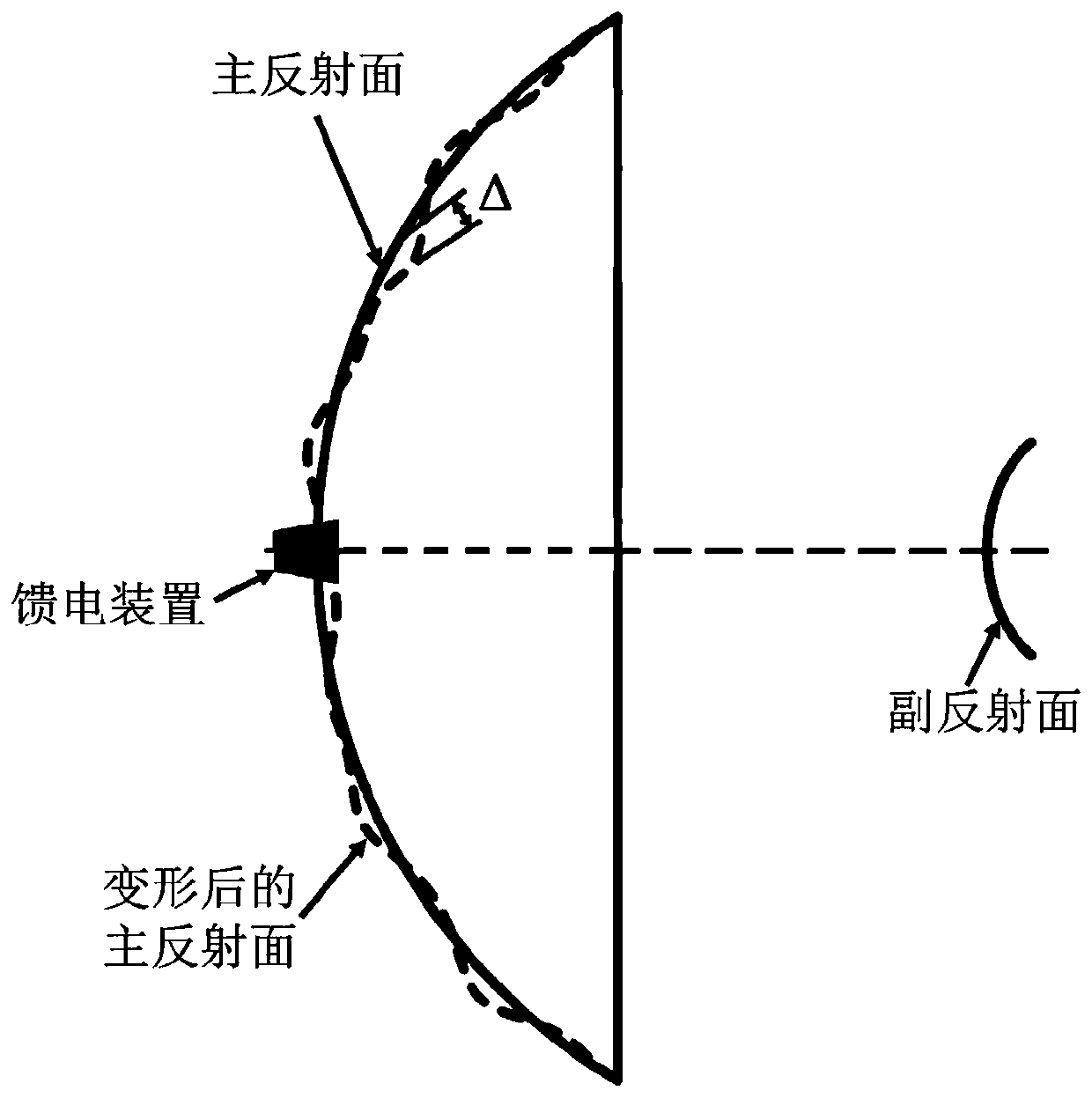
[0064] by figure 2 The antenna shown is an example. The precision error generated by the antenna structure under the action of external forces such as self-weight and wind load will change the distribution of the electromagnetic amplitude and phase of the antenna aperture. The red dotted line in the figure indicates the deformed reflecting surface, and the shape error Δ will eventually affect the far-field electrical performance of the antenna. .

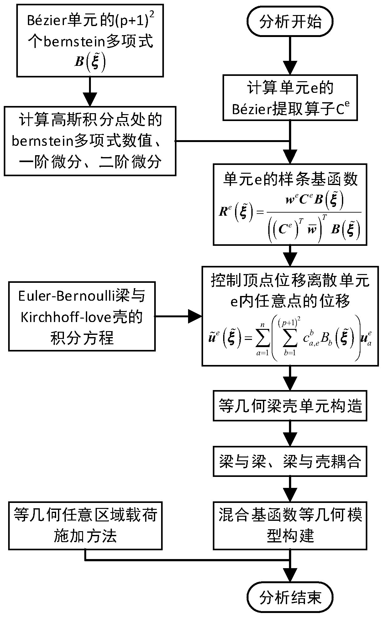
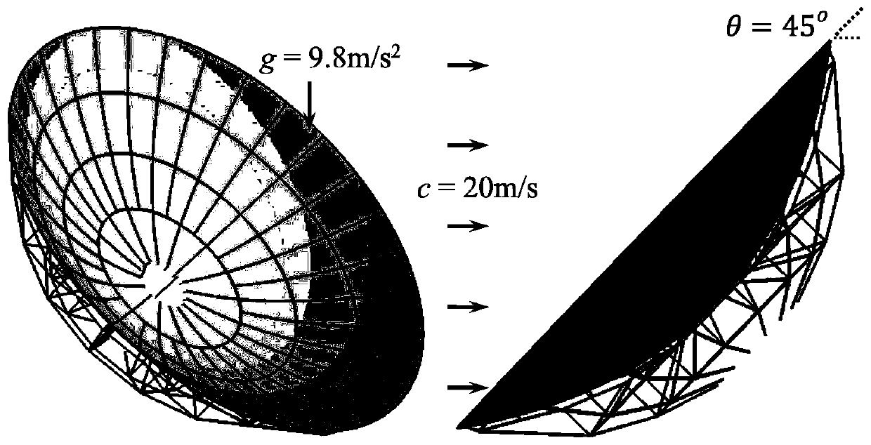
[0065] (1) Use the Euler-Bernoulli beam element based on NURBS and the Kirchhoff-Love shell element based on unstructured T-splines to construct the truss and reflector of the antenna structure, such as image 3 , the yellow part is the main reflector, and the blue part is the antenna support. Analyze the shape error of the reflector antenna under the action of gravi...


PUM


Abstract

The invention discloses an antenna model load displacement measurement method of a mixed basis function. The method comprises the steps: constructing a beam unit by using an NURBS primary function forthe beam, calculating a Bessel extraction operator of the basic unit, and coupling a beam-beam unit and a beam-shell unit; establishing and arranging a constraint equation; judging and setting a displacement coefficient matrix according to a coupling relation among different basic units; fusing the displacement constraint equation into the system stiffness matrix of the whole isogeometric model by adopting a penalty function method, establishing a corrected potential energy functional considering a penalty function, and solving the final system balance equation to obtain the displacement of the antenna control vertex. According to the method, different structural types of components of different spline basis function discrete array element antenna complex products are adopted, so that themodeling flexibility of a product model is improved.

Description

technical field [0001] The invention relates to a method for measuring the load displacement of a complex product model, in particular to a method for measuring the load displacement of an antenna model with a mixed basis function. Background technique [0002] Antennas are complex industrial products composed of various structural types, with large dimensions, including shells, beams, rods and other structures. The geometric complexity of different structures is different, and the difficulty of constructing their isogeometric models is also different. For example, the beam structure can often be simplified, and the overall physical properties can be represented by its neutral layer curve. Therefore, NURBS is sufficient to construct the isogeometric model of the beam. However, the shell structure usually cannot be described by a single NURBS or Hermite surface patch, and T-splines are more suitable for the isogeometric basis function of the shell structure. [0003] For th...

Claims


Application Information

Patent Timeline
IPC IPC(8): G06F30/20G06F111/10
Inventor 刘振宇袁沛杨明龙裘辿谭建荣
Owner ZHEJIANG UNIV
Why Eureka
Try Eureka