Low-current grounding capacitance current online measurement system
A low-current grounding, capacitive current technology, applied in voltage/current isolation, using digital measurement technology for measurement, changing range circuits, etc. The effect of voltage measurement level, saving operation and maintenance costs, and improving compensation effect
- Summary
- Abstract
- Description
- Claims
- Application Information
AI Technical Summary
Problems solved by technology
Method used
Image
Examples
specific Embodiment approach 1
[0042] Embodiment 1: When the switch S in the arc suppressing coil 3 is closed, that is, when the arc suppressing coil 3 is put into operation, the improved maximum displacement voltage method is used to measure and calculate the small current grounding capacitor current, combined with Figure 8 The measurement flow chart shown, the main steps are as follows:
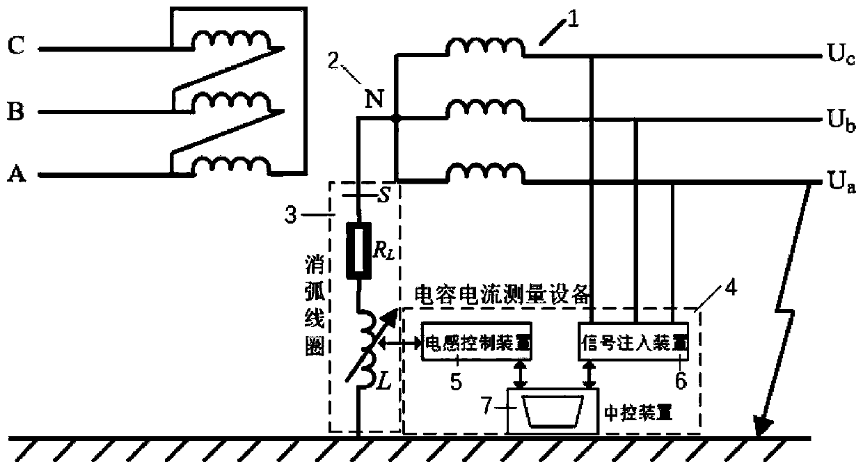
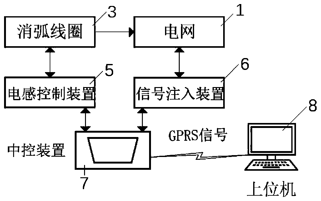
[0043] Step 1: The central control device 7 is put into operation through the inductance control device 5, and the signal injection device 6 is closed; if figure 1 As shown, at this moment, the inductance control device 5 controls the arc suppression coil 3 to complete the measurement of the capacitive current;
[0044] Step 2: If Figure 5 , the stepper motor inside the inductance control device 5 is connected to control the adjustable inductance L of the arc suppression coil 3. During the process of increasing the arc suppression coil L, the arc suppression coil is controlled by the high and low range voltage sensor ...
specific Embodiment approach 2
[0057] Specific embodiment two: when the switch S in the arc suppressing coil 3 is turned off, that is, when the arc suppressing coil 3 is not put into operation, the improved maximum displacement voltage method cannot be used to measure and calculate the small current grounding capacitor current at this time, so it can be used The signal injection method is used to measure the capacitive current, combined with Figure 12 The measurement flow chart shown, the main steps are as follows:.
[0058] Step 1: The central control device 7 is put into operation through the signal injection device 6, and the inductance control device 5 is turned off; if figure 1 As shown, at this time, the signal injection device 6 performs signal injection to the grid line 1 to complete the measurement of the capacitive current;
[0059] Step 2: If Figure 7 , the voltage transformer 305 in the measurement unit 12 of the injection device measures the system frequency and the displacement voltage U ...
PUM
 Abstract
Description
Claims
Application Information
 - Generate Ideas
- Intellectual Property
- Life Sciences
- Materials
- Tech Scout
- Unparalleled Data Quality
- Higher Quality Content
- 60% Fewer Hallucinations
Browse by: Latest US Patents, China's latest patents, Technical Efficacy Thesaurus, Application Domain, Technology Topic, Popular Technical Reports.
© 2025 PatSnap. All rights reserved.Legal|Privacy policy|Modern Slavery Act Transparency Statement|Sitemap|About US| Contact US: help@patsnap.com


