
Blasting expanding element special for underground blasting engineering

A technology of blasting engineering and components, which is applied in the direction of blasting, etc., can solve the problems of inability to solve the problem of detonator or explosive rejection, hidden safety hazards of blind shot disposal, high cost, etc., and achieve the effect of excellent detonation performance, excellent detonation performance and low manufacturing cost

Active Publication Date: 2020-06-05
YAHUA GROUP MIANYANG INDAL
View PDF7 Cites 0 Cited by
  • Summary
  • Abstract
  • Description
  • Claims
  • Application Information

AI Technical Summary

Problems solved by technology

[0004] At present, although individual units at home and abroad have developed a high-power detonator detonator, although it can detonate explosives without detonator sensitivity, it still cannot solve the problem of detonation rejection of underground blasting, especially tunnel blasting engineering detonators or explosives due to structural reasons, and the cost On the high side, the powder column can be taken out, which also brings pressure to public safety and product storage, and brings greater safety hazards to blind shot disposal

Method used


Image

  • Blasting expanding element special for underground blasting engineering
  • Blasting expanding element special for underground blasting engineering
  • Blasting expanding element special for underground blasting engineering

Examples


Embodiment 1

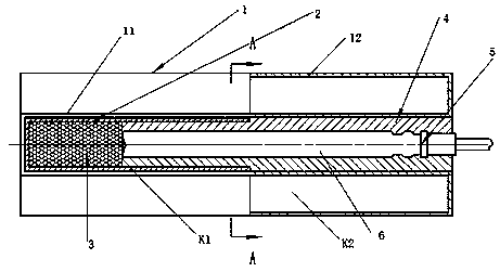
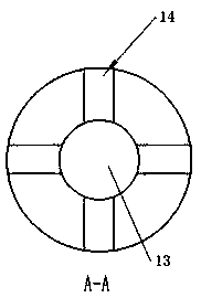
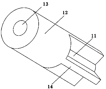
[0031] see Figure 1-5 , a special explosion expansion element for underground blasting engineering, including a fixed block 1, the fixed block 1 is divided into two parts: a wing section 11 and a barrel section 12, the fixed block 1 is provided with a fixed block center hole 13, and the fixed block The central hole 13 runs through the wing section 11 and the barrel section 12, and the end of the wing section 11 away from the barrel section 12 is closed, and four fin blocks 14 are evenly arranged on the periphery of the center hole 13 of the fixing block of the wing section 11, correspondingly The included angle between two adjacent fin blocks 14 is 90°, and the outer circumference of the fin block 14 is flush with the outer circumference of the barrel section 12;

[0032] It also includes an expansion charge shell 2, the expansion charge shell 2 is press-fitted with an expansion charge 3, and the expansion charge shell 2 is located in the wing section of the central hole 13 o...

Embodiment 3

[0041] In this embodiment, there are six fin blocks, and the angle between two adjacent fin blocks is 60°, and the rest are the same as in Embodiment 1.


PUM


Abstract

The invention discloses a blasting expanding element special for underground blasting engineering, and belongs to the field of blasting instruments and the blasting engineering. The blasting expandingelement comprises a fixing block. The fixing block comprises a sub-fin section and a barrel section. The fixing block is provided with a fixing block center hole, the fixing block center hole penetrates through the sub-fin section and the barrel section, the end, away from the barrel section, of the sub-fin section is closed, and 3-6 fin blocks are arranged on the portion, on the periphery of thefixing block center hole, of the sub-fin section. The blasting expanding element further comprises a blasting expanding powder column pipe shell, a blasting expanding powder column is pressed in theblasting expanding powder column pipe shell, and the blasting expanding powder column pipe shell is located at the position, at the bottom of the sub-fin section, of the center hole. The blasting expanding element further comprises a sealing plug, a sealing plug center hole is formed in the center of the sealing plug, and the sealing plug is arranged in the fixing block center hole and makes contact with the end face of the blasting expanding powder column. Automatic assembly can be achieved, the production efficiency is high, the cost is low, and meanwhile the problems that in the undergroundblasting engineering, as detonation waves compress adjacent detonators, blasting failure or a groove effect is caused, and explosive is under blasting failure are solved.

Description

technical field [0001] The invention relates to the fields of blasting equipment and blasting engineering, in particular to a special explosion expansion element for underground blasting engineering. Background technique [0002] With the increasing industrial concentration of China's civil explosives industry, the individualization of blasting equipment and the development of engineering blasting technology, various low-sensitivity explosives such as mixed explosives have become the dominant direction of blasting materials, and it is also the national public security's proposal for explosives. strict requirements. For this trend, it is not the best choice to expand the detonation energy of the detonator itself. The traditional method is to use a detonator, but the detonator has a complicated manufacturing process, high cost and uses toxic explosive materials such as TNT. [0003] In addition, in underground blasting, especially tunnel blasting, there are often detonation w...

Claims


Application Information

Patent Timeline
Patent Type & Authority Applications(China)
IPC IPC(8): F42D1/04
CPCF42D1/04
Inventor 马志刚罗伟任春培郭红莉
Owner YAHUA GROUP MIANYANG INDAL
Learn More