Device used for monitoring microwave vacuum drying

A technology of microwave vacuum drying and microwave cavity, which is applied in heating devices, measuring devices, drying solid materials, etc., can solve the problems of affecting the accuracy of experiments, affecting the continuity of experiments, and little research on material color and shape changes. Effect of Physical Quality and Chemical Composition

Inactive Publication Date: 2020-06-05
SHAANXI UNIV OF SCI & TECH
View PDF5 Cites 4 Cited by
  • Summary
  • Abstract
  • Description
  • Claims
  • Application Information

AI Technical Summary

Problems solved by technology

[0002] As a new type of drying technology, microwave vacuum drying technology has not been thoroughly studied by researchers on its basic principles, and the research on the drying process of materials is not deep enough, especially on the color and shape changes of materials during the drying process.
Some existing studies also need to take the materials out of the drying equipment, and then put them back into the drying equipment to continue drying after image collection. This not only affects the continuity of the experiment, but also destroys the stable drying environment required for material drying, and frequently picks and places materials. It will also make the material come into contact with the air during the drying process, which is not conducive to the accuracy of the experiment
Manually pick and place materials for image acquisition, and the grasp of the time interval is not accurate. For a rapid drying method such as microwave vacuum, it will bring inevitable errors, thus affecting the accuracy of the experiment.
[0003] Furthermore, due to the particularity of the heating method, microwave heating will resonate with polar molecules such as water molecules, and it is easy to generate heat accumulation in the place where the moisture concentration of the material is concentrated, resulting in scorching of the material during the drying process, which is not conducive to the drying of the material. quality improvement

Method used


Image

  • Device used for monitoring microwave vacuum drying
  • Device used for monitoring microwave vacuum drying
  • Device used for monitoring microwave vacuum drying

Examples


Embodiment Construction

[0028] The present invention will be described in further detail below in conjunction with the accompanying drawings.

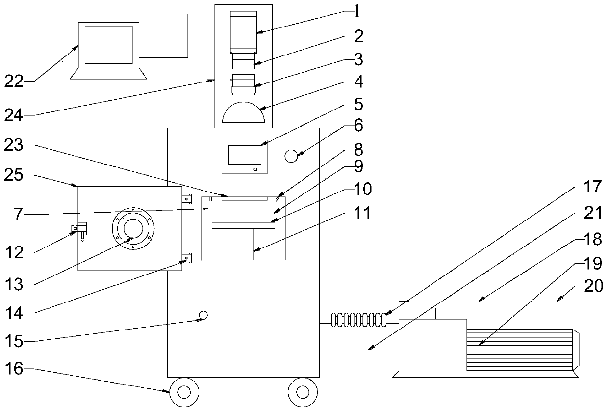
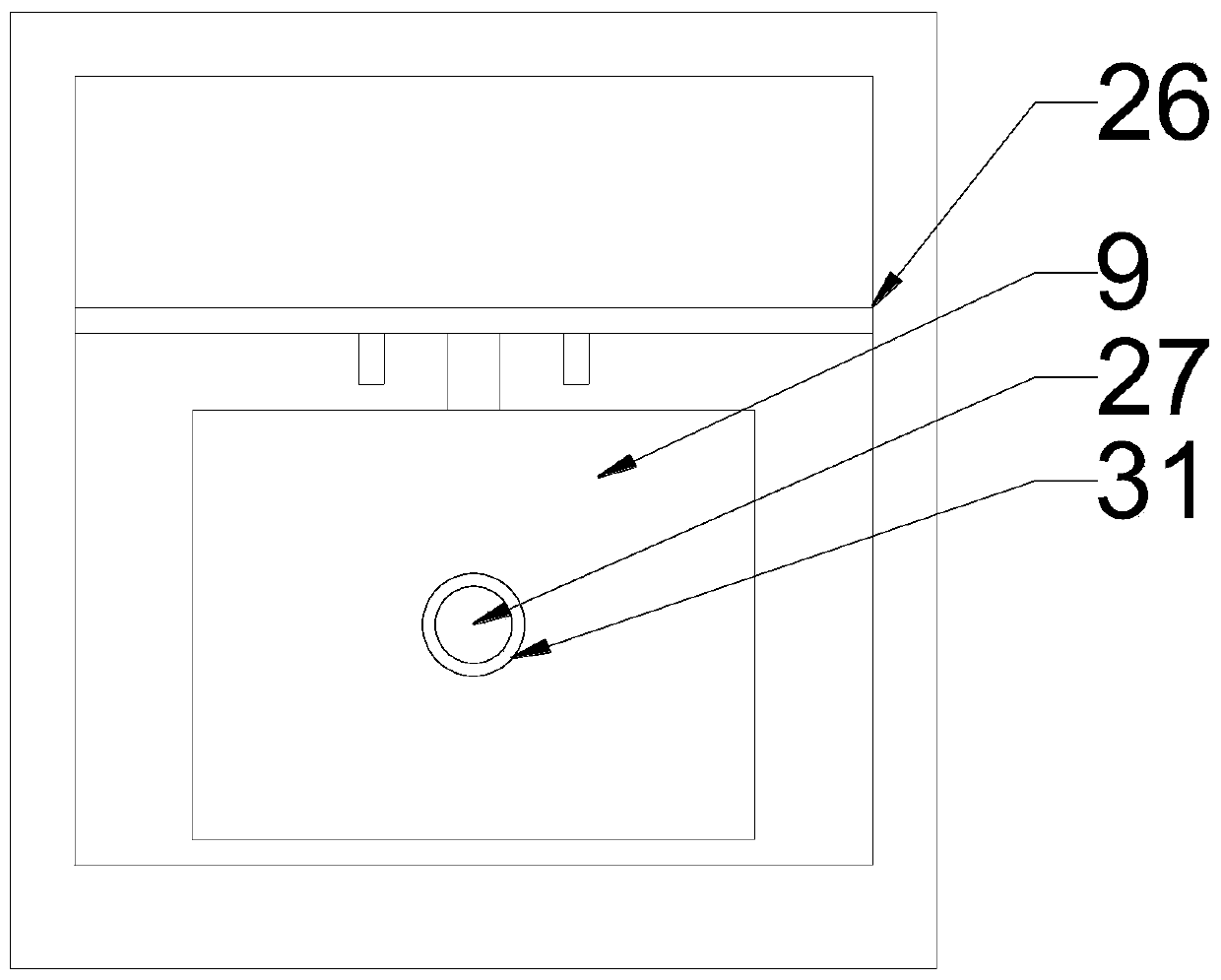
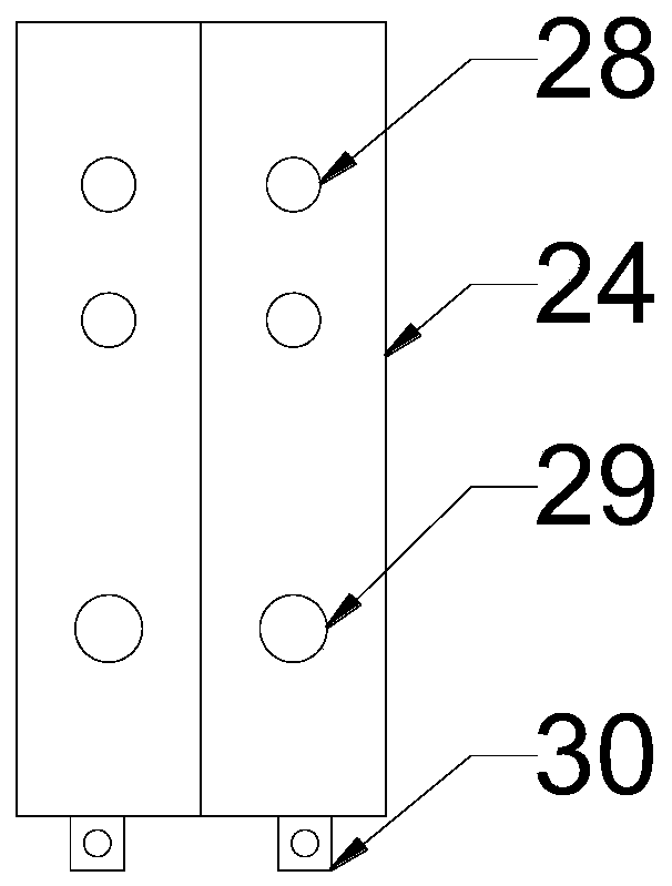
[0029] Such as figure 1 Shown: a device for monitoring microwave vacuum drying, including a drying system, a vacuum system and an image acquisition system; the drying system includes an output control system, a microwave system, a weighing system and a temperature measurement system, and the microwave system mainly Comprising a microwave chamber 9, a microwave generator 23 and a drying chamber door 25, the microwave generator 23 is located above the inner wall of the microwave chamber 9, and the microwave chamber 9 is connected with an exhaust hole 15, so that after drying The microwave chamber 9 is returned to atmospheric pressure, and an observation hole 13 is provided on the door 25. The weighing system includes a tray support 11, a tray 10 and a weighing sensor, and the weighing system is located in the microwave oven. In the middle position in the chamb...


PUM


Abstract

The invention discloses a device used for monitoring microwave vacuum drying. The device comprises a drying system, a vacuum system and an image acquisition system, wherein the drying system comprisesan output control system, a microwave system, a weighing system and a temperature measuring system; the microwave system comprises a microwave generator which is positioned above the inner wall of amicrowave cavity; a gas exhaust hole and a drying room cabin door are arranged on the microwave cavity; the weighing system is positioned in the microwave cavity; the temperature measuring system is positioned above the inner wall of the microwave cavity; the output control system is used for controlling the microwave system, the vacuum system, the weighing system and the temperature measuring system; the vacuum system is used for performing vacuum treatment on the microwave cavity; the temperature measuring system is used for detecting a temperature inside the microwave cavity; and the imageacquisition system is used for monitoring a condition inside the microwave cavity. The device can perform image acquisition at an accurate time interval, also can record the whole drying process, improves experimental accuracy, and further performs real-time monitoring for the drying process.

Description

technical field [0001] The invention relates to the technical field of drying equipment, in particular to a device for monitoring microwave vacuum drying. Background technique [0002] As a new type of drying technology, microwave vacuum drying technology has not been thoroughly studied by researchers on its basic principles, and the research on the drying process of materials is not deep enough, especially on the color and shape changes of materials during the drying process. Some existing studies also need to take the materials out of the drying equipment, and then put them back into the drying equipment to continue drying after image collection. This not only affects the continuity of the experiment, but also destroys the stable drying environment required for material drying, and frequently picks and places materials. It will also make the material come into contact with the air during the drying process, which is not conducive to the accuracy of the experiment. Manuall...

Claims


Application Information

Patent Timeline
Patent Type & Authority Applications(China)
IPC IPC(8): F26B9/06F26B3/347F26B5/04F26B23/08F26B25/00F26B25/22H04N7/18H04N5/76G01J5/00G01G19/62G01N21/84
CPCF26B3/347F26B5/048F26B9/06F26B23/04F26B25/00F26B25/22G01G19/62G01J5/00G01N21/84G01N2021/8411H04N5/76H04N7/183
Inventor 董继先温家豪王栋刘瑞王怡王慧
Owner SHAANXI UNIV OF SCI & TECH
Why Eureka
Try Eureka