
High-pressure slide valve type check valve

A high-pressure slide valve and one-way valve technology, applied in the field of one-way hydraulic valves, can solve the problems of increased vibration and noise of the hydraulic system, poor opening speed, and shortened service life, so as to reduce the leakage of hydraulic oil and avoid the flow of hydraulic oil. Empty, fast-moving and smooth effects

Pending Publication Date: 2020-06-05
WUHAN UNIV OF SCI & TECH
View PDF3 Cites 0 Cited by
  • Summary
  • Abstract
  • Description
  • Claims
  • Application Information

AI Technical Summary

Problems solved by technology

[0002] At present, check valves are commonly used in hydraulic systems, and their spool structures are mostly conical or spherical. Most of the existing check valve spools and valve seats are in line contact, which is prone to spool misalignment, and Due to frequent opening and closing and vibration, the joints are easy to wear and tear, resulting in grooves, affecting the sealing performance, making the one-way valve unstable and reducing the service life
And because the hydraulic system is in high-frequency vibration, the one-way valve is also in high-frequency vibration at this time, which makes the valve core and the valve seat produce impact, thereby increasing the vibration and noise of the hydraulic system and affecting the working performance of the hydraulic system.
To open the high-pressure check valve, a small unloading valve needs to be added, which makes the structure of the high-pressure check valve more complicated.
[0003] From the current research situation, it is found that many scholars use software such as fluent to simulate the flow of the check valve, and make some improvements to the structure, which effectively solves the shortcomings of loud noise, easy jamming, and poor opening speed. However, the valve core structure Most are still spherical or conical
"A hydraulically controlled one-way valve (CN209725330)" discloses a hydraulically controlled one-way valve with an improved structure, which improves the contact performance between the spherical surface and the through hole, but the sealing performance still needs to be improved; "Ultra-high pressure hydraulically controlled one-way valve Directional valve (CN209469836U) " discloses a kind of one-way valve that works under ultra-high pressure, is provided with a kind of piston that can be driven by liquid, can assist ball core motion; " a kind of high-pressure one-way valve ( CN209761891U)" discloses a check valve controlled by an electromagnet, which improves the automatic control level of the check valve, and has the characteristics of not being affected by oil return back pressure, fast response speed and no need to control the oil circuit
However, in the above-mentioned technologies, the valve core is a spherical or conical structure, and the connection between the valve core and the valve seat is still in line contact. Under mechanical impact and hydraulic impact, it is easy to cause wear on the contact surface, poor sealing performance, and shorten the service life.

Method used


Image

  • High-pressure slide valve type check valve
  • High-pressure slide valve type check valve
  • High-pressure slide valve type check valve

Examples


Embodiment 1

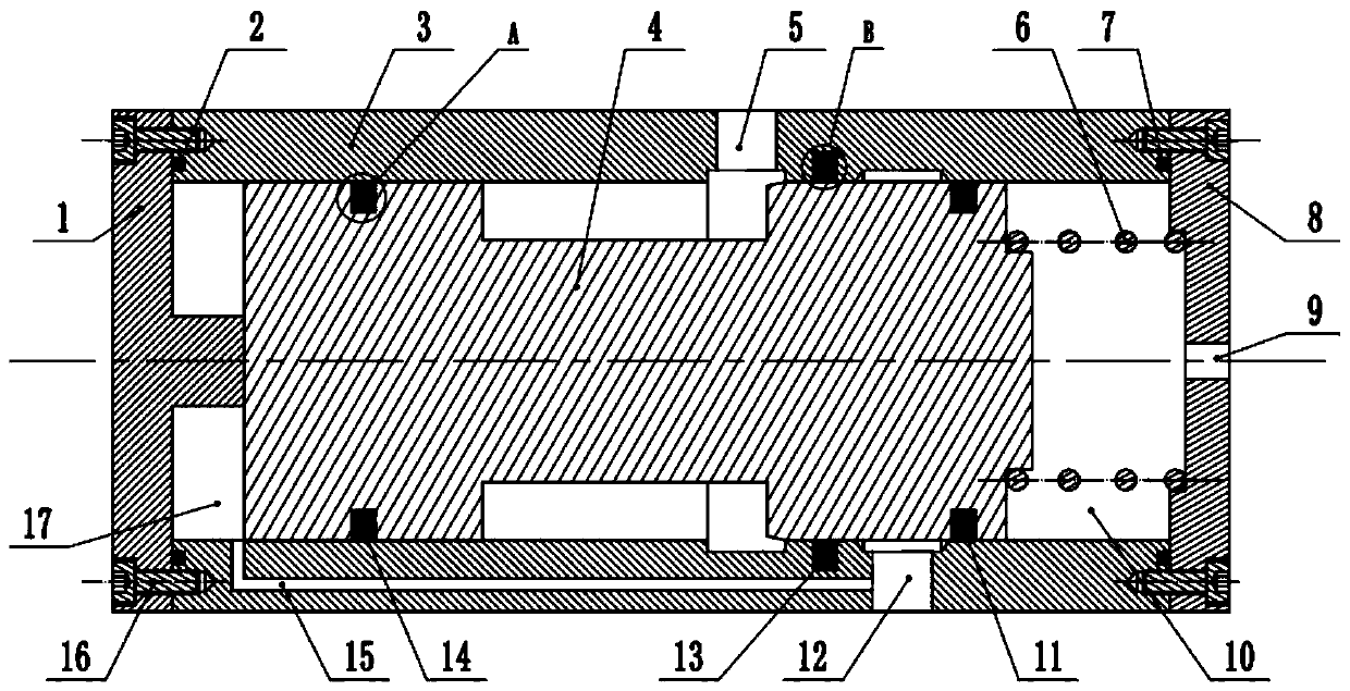
[0052] A high pressure spool type check valve. Such as figure 1 As shown, the high-pressure slide valve check valve includes a valve body 3 , a valve core 4 , a spring 6 , a left valve cover 1 and a right valve cover 8 . The left valve cover 1 and the right valve cover 8 are installed on the corresponding left and right ends of the valve body 3 through bolts 16. The valve body 3 is equipped with a valve core 4 and a spring 6. One end of the spring 6 is in contact with the right valve cover 8, and the spring 6 The other end is in contact with the right end of the spool 4; the right cylindrical surface of the spool 4 is equipped with a first combination sealing ring 11, the middle part of the inner wall of the valve body 3 is equipped with a second combination sealing ring 13 on the right side, and the left side of the spool 4 The third combined sealing ring 14 is installed on the cylindrical surface; the left sealing ring 2 and the right sealing ring 7 are respectively install...

Embodiment 2

[0064] A high pressure spool type check valve. Except following technical parameter, all the other are with embodiment 1:

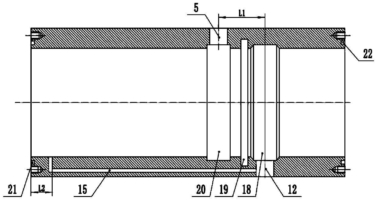
[0065] The distance L1 between the extension line of the center line of the first oil port 5 and the extension line of the center line of the second oil port 12 is 30-40mm.

[0066] The included angle between the annular slope and the inner wall is 42-45°

[0067] The distance L2 between the oil outlet of the control oil passage 15 and the left end surface of the valve body 3 = 22-25mm;

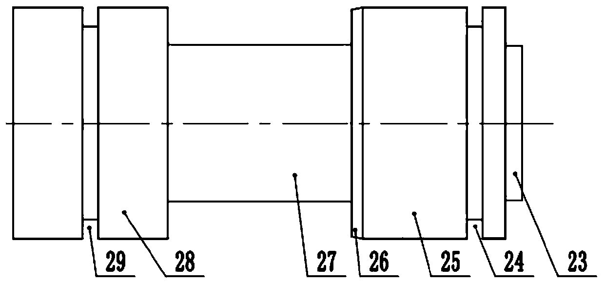
[0068] The gap between the diameter of the left cylinder 28 and the right cylinder 25 of the valve core 4 and the inner wall of the valve body 3 is 7-10 μm.

[0069] The free length of the spring 6 is 55-80 mm, and the compression amount is 30-40 mm.

[0070] Compared with the prior art, this specific embodiment has the following advantages:

[0071] 1. When the high-pressure oil enters from the second oil port 12 and enters the left chamber 17 through the control oi...


PUM


Abstract

The invention belongs to the technical field of one-way hydraulic valves, and particularly relates to a high-pressure slide valve type check valve. According to the technical scheme, the high-pressureslide valve type check valve includes a valve body (3), a valve core (4), a spring (6), a left valve cover (1) and a right valve cover (8); the left valve cover (1) and the right valve cover (8) areinstalled on the corresponding left end and the corresponding right end of the valve body (3) through bolts (16), the valve body (3) is internally provided with the valve core (4) and the spring (6),one end of the spring (6) is in contact with the right valve cover (8), the other end of the spring (6) is in contact with the right end of the valve core (4); a first combined seal ring (11) is installed on the right cylindrical surface of the valve core (4), a second combined seal ring (13) is installed at the position, close to the right, of the middle part of the inner wall of the valve body (3), and a third combined seal ring (14) is installed on the left cylindrical surface of the valve core (4); and a left seal ring (2) and a right seal ring (7) are correspondingly installed on the leftend surface and the right end surface of the valve body (3). The high-pressure slide valve type check valve has the characteristics of no hydraulic and mechanical impact, tight sealing, good stability and long service life.

Description

technical field [0001] The invention belongs to the technical field of one-way hydraulic valves. In particular, it relates to a high-pressure slide valve type check valve. Background technique [0002] At present, check valves are commonly used in hydraulic systems, and their spool structures are mostly conical or spherical. Most of the existing check valve spools and valve seats are in line contact, which is prone to spool misalignment, and Due to frequent opening and closing and vibration, the joints are easy to wear and tear, resulting in grooves, which affect the sealing performance, make the one-way valve work unstable, and reduce the service life. And because the hydraulic system is in high-frequency vibration, the check valve is also in high-frequency vibration at this time, which makes the valve core and the valve seat produce impact, thereby increasing the vibration and noise of the hydraulic system and affecting the working performance of the hydraulic system. To...

Claims


Application Information

Patent Timeline
Patent Type & Authority Applications(China)
IPC IPC(8): F15B13/02F16K31/363F16K27/04F16K3/314
CPCF15B13/027F16K31/363F16K27/041F16K3/314
Inventor 湛从昌陈兵邓江洪叶文杰陈新元郭媛
Owner WUHAN UNIV OF SCI & TECH
Learn More