Energy dissipation structure for water conservancy and hydropower engineering

A water conservancy, hydropower and engineering technology, applied in water conservancy projects, marine engineering, coastline protection, etc., can solve the problems of wear and tear, weakened energy dissipation effect, etc., and achieve the effect of increasing the contact area, increasing the angle range, and increasing the implementability.

Active Publication Date: 2020-06-05
湖南中信水电建设有限公司
View PDF8 Cites 0 Cited by
  • Summary
  • Abstract
  • Description
  • Claims
  • Application Information

AI Technical Summary

Problems solved by technology

[0004] The above existing technical solutions have the following defects: the structures such as stone piers, steps and retaining columns will be continuously worn under the long-term erosion of water flow, so that the energy dissipation effect will gradually weaken

Method used


Image

  • Energy dissipation structure for water conservancy and hydropower engineering
  • Energy dissipation structure for water conservancy and hydropower engineering
  • Energy dissipation structure for water conservancy and hydropower engineering

Examples


Embodiment Construction

[0034] The present invention will be described in further detail below in conjunction with the accompanying drawings.

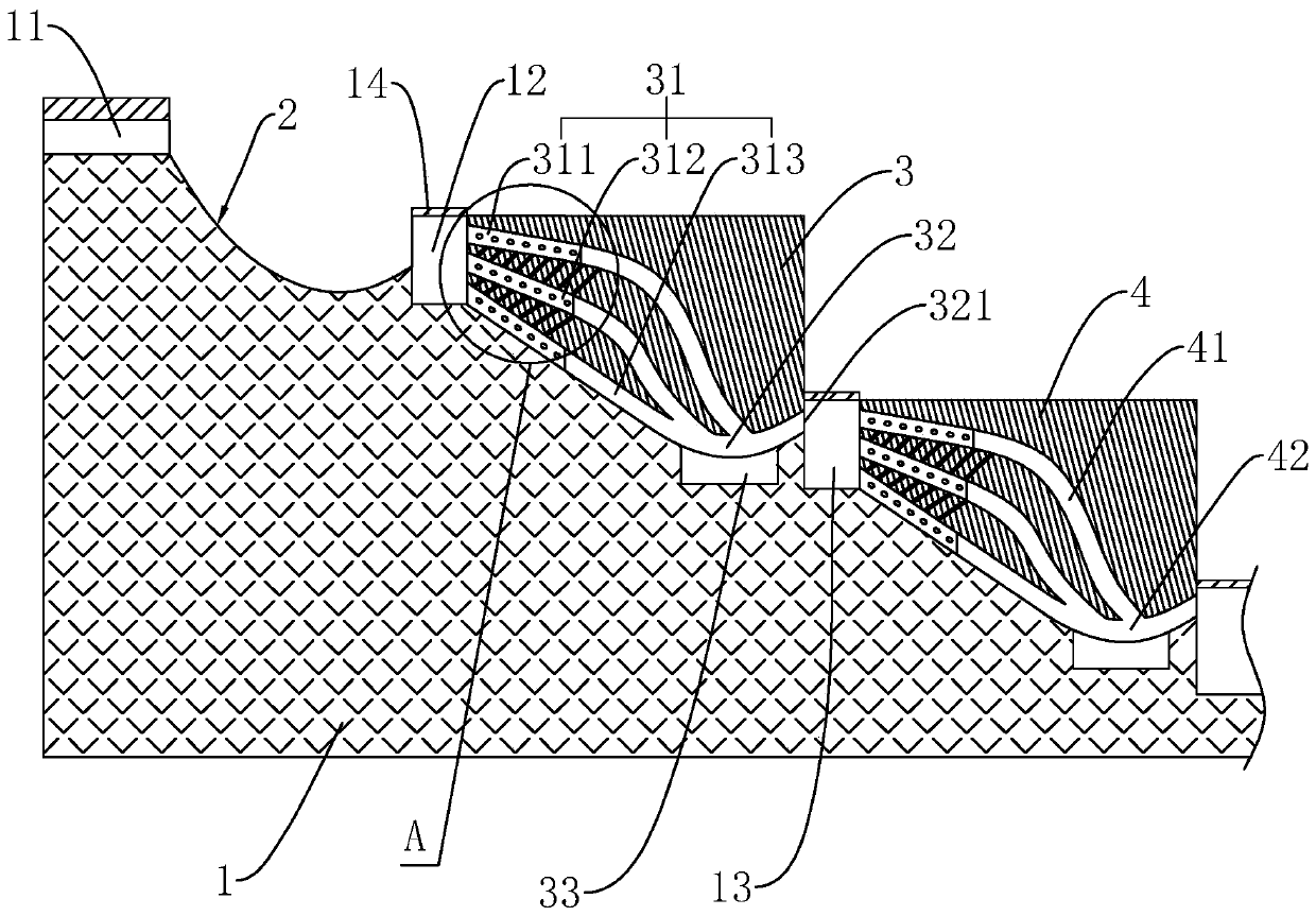
[0035] This embodiment discloses an energy dissipation structure for water conservancy and hydropower projects, such as figure 1 As shown, it includes a discharge outlet 11 arranged on the top of the dam 1, a deflector ramp 2 arranged on the downstream side of the dam 1, the upper end of the deflector ramp 2 connects to the discharge outlet 11, and the lower end extends obliquely downward and At the end, it tilts up obliquely along the arc. A plurality of buffer devices such as the first buffer device 3 , the second buffer device 4 , and the third buffer device are arranged in sequence along the water flow direction below the deflecting ramp 2 , and the deflecting ramp 2 is used to project the downwardly pouring water flow upwards. In the air, use the air to dissipate part of the kinetic energy of the water flow; then use multiple buffer devices to dissipate...


PUM


Abstract

The invention aims to provide an energy dissipation structure for water conservancy and hydropower engineering. The energy dissipation structure involves a drainage port formed in the upper portion ofa dam and a flip ramp arranged on one side of the dam; the upper end of the flip ramp is connected with the drainage port, and the lower end of the flip ramp obliquely extends downwards and tilts upwards along an arc at the end part; a buffer device is arranged at the tail end of the flip ramp, and a hydraulic jump area is arranged between the buffer device and the flip ramp; the end face, facingthe flip ramp, of the buffer device is provided with a plurality of continuous flowing channels arranged from top to bottom; and a water outlet communicating with all the continuous flowing channelsis formed in the end surface, back on to the flip ramp, of the buffer device. The downwards-poured water flow is upwards flipped into the air through the flip ramp, and part of kinetic energy of the water flow is dissipated through the air; and when the water flow passes through the hydraulic jump area from the air, the diffusion phenomenon can be generated, so that the water flow can enter the continuous flowing channels with different heights, the contact area between the continuous flowing channels and the water flow is increased, and energy dissipation is conducted on the water flow through friction force.

Description

technical field [0001] The invention relates to the technical field of water conservancy and hydropower projects, in particular to an energy dissipation structure for water conservancy and hydropower projects. Background technique [0002] With the gradual development of hydropower resources in mountainous rivers in my country, the development of my country's hydropower engineering construction has entered a climax stage, especially in the western mountainous areas where a large number of small and medium hydropower stations have been built. The water flow in natural rivers is generally a slow flow, and the single-width flow distribution along the river width is relatively uniform. However, when drainage structures such as dams and sluices are built in the river, the flow conditions of the river have undergone tremendous changes, and the flow velocity and energy of the discharged water are large, which has a great destructive effect on the riverbed downstream of the drainage...

Claims


Application Information

Patent Timeline
IPC IPC(8): E02B8/06
CPCE02B8/06
Inventor 邓新洪张红俊谭方伟
Owner 湖南中信水电建设有限公司
Why Eureka
Try Eureka