
Bearing roller anti-bumping trigger box and anti-bumping method

A bearing roller and anti-collision technology, which is applied in the field of material boxes, can solve the problems of the rollers being difficult to collide with each other and cooperate with loading, so as to achieve the effect of reducing collision, reducing collision and high tolerance

Pending Publication Date: 2020-06-05
ZHANGJIAGANG AAA BEARING
View PDF0 Cites 2 Cited by
  • Summary
  • Abstract
  • Description
  • Claims
  • Application Information

AI Technical Summary

Problems solved by technology

[0005] One of the objectives of the present invention is to solve the problem that the charging box in the prior art cannot reduce the collision between the rollers and is difficult to cooperate with the existing feeding equipment for charging

Method used


Image

  • Bearing roller anti-bumping trigger box and anti-bumping method
  • Bearing roller anti-bumping trigger box and anti-bumping method
  • Bearing roller anti-bumping trigger box and anti-bumping method

Examples


Embodiment 1

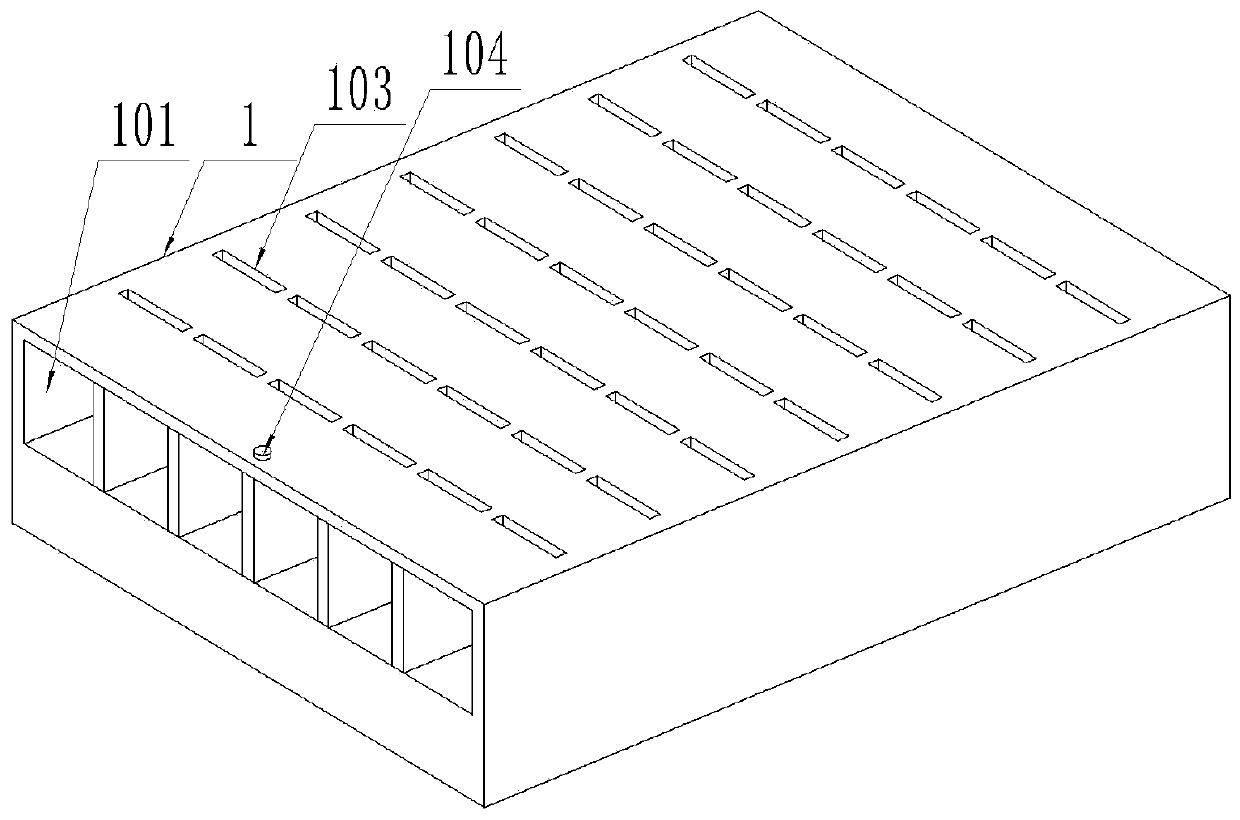
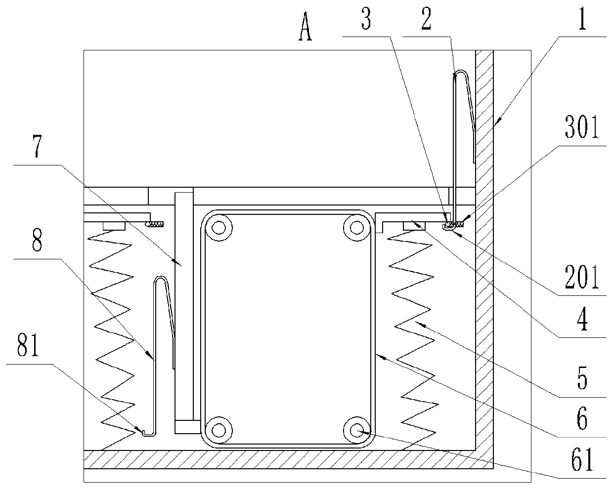
[0058] A bearing roller anti-collision trigger box, wherein, such as Figure 1-6 As shown, it includes: a box body 1 , a first elastic piece 2 , a limiting portion 3 , a return spring 301 , a pressure portion 4 , a tension spring 5 , a reversing belt 6 , a trigger plate 7 , and a second elastic piece 8 .

[0059] Such as figure 2 As shown, the box body 1 has a raceway 101 and a trigger space 102, the left end of the raceway 101 communicates with the outside world, and the right end of the raceway 101 has a wall to block it. The trigger space 102 has a connection port 1021 , and the connection port 1021 communicates with the trigger space 102 and the raceway 101 .

[0060] Such as image 3 As shown, the right end of the first elastic piece 2 is arranged on the right end wall surface of the raceway 101, the left side of the first elastic piece 2 extends into the trigger space 102, the first elastic piece 2 has a first hook 201, and the first hook 201 is formed by The lower l...


PUM


Abstract

The invention discloses a bearing roller anti-bumping trigger box, and relates to the technical field of material boxes. The bearing roller anti-bumping trigger box comprises a box body, a first elastic piece, limiting parts, a reset spring, a pressure part, a tension spring, a reversing belt, trigger plates and a second elastic piece. The pressure part abuts against the limiting parts, the tension spring is connected with the pressure part, and the reversing belt is connected with the trigger plates and the pressure part. According to the bearing roller anti-bumping trigger box, the first elastic piece bears the kinetic energy deformation of a bearing roller to pull the limiting part to move, so that the pressure part pulls the reversing belt to move downwards to drive the trigger platesto extend out of a rollway nest, and the second elastic piece hooks another limiting part to form a new trigger point to replace the first elastic piece. Through the disconnected trigger mode, each bearing roller can be limited in a square to be protected every time, and mutual bumping of the bearing rollers is avoided; and meanwhile, after each trigger, each trigger plate can buffer according toeach bearing roller, and bumping of the bearing rollers is greatly reduced.

Description

technical field [0001] The invention relates to the technical field of material boxes, in particular to an anti-collision trigger box for bearing rollers. Background technique [0002] At present, during the manufacture and processing of rollers for bearings, when the roller grinder is finished off the assembly line, the processed rollers are manually loaded. [0003] Due to the improper operation of the loading personnel during the loading process, the rollers may have strong collisions with each other (vibration is very sensitive to bearing damage, peeling, indentation, rust, cracks, wear, etc. Reflected in the bearing vibration measurement), scratch the roller. In addition, the existing charging box is difficult to cooperate with the automatic feeding equipment, because the existing automatic feeding equipment usually pushes the rollers one by one into the swinging box or makes the rollers enter the charging box through gravity, However, the current roller boxes are usu...

Claims


Application Information

Patent Timeline
Patent Type & Authority Applications(China)
IPC IPC(8): B24B41/00B65D25/06B65D25/10
CPCB24B41/00B65D25/06B65D25/108
Inventor 顾新忠周良良徐鹏飞朱斌
Owner ZHANGJIAGANG AAA BEARING
Learn More