
A device for grinding end face of crank connecting rod

A technology of end face grinding and crank connecting rod, which is applied in the directions of grinding/polishing safety device, grinding feed motion, grinding workpiece support, etc., which can solve the problems of batch processing and low efficiency.

Active Publication Date: 2021-04-27
扬州创盟自行车配件有限公司
View PDF11 Cites 0 Cited by
  • Summary
  • Abstract
  • Description
  • Claims
  • Application Information

AI Technical Summary

Problems solved by technology

[0003] After the crank connecting rod is forged, the end faces of the large round end and the small round end need to be polished. At present, the existing equipment can only process the end faces of the crank connecting rod one by one, and cannot process them in batches, so the efficiency is low.

Method used


Image

  • A device for grinding end face of crank connecting rod
  • A device for grinding end face of crank connecting rod
  • A device for grinding end face of crank connecting rod

Examples


Embodiment Construction

[0039] In order to make the object, technical solution and advantages of the present invention clearer, the present invention will be further described in detail below in conjunction with the accompanying drawings and embodiments. It should be understood that the specific embodiments described here are only used to explain the present invention, not to limit the present invention.

[0040] In the description of the present invention, it should be noted that the terms "center", "upper", "lower", "left", "right", "front", "rear", "vertical", "horizontal", The orientation or positional relationship indicated by "inner", "outer", etc. is based on the orientation or positional relationship shown in the drawings, and is only for the convenience of describing the present invention and simplifying the description, rather than indicating or implying that the referred device or element must have Certain orientations, constructed and operative in certain orientations, therefore are not t...


PUM


Abstract

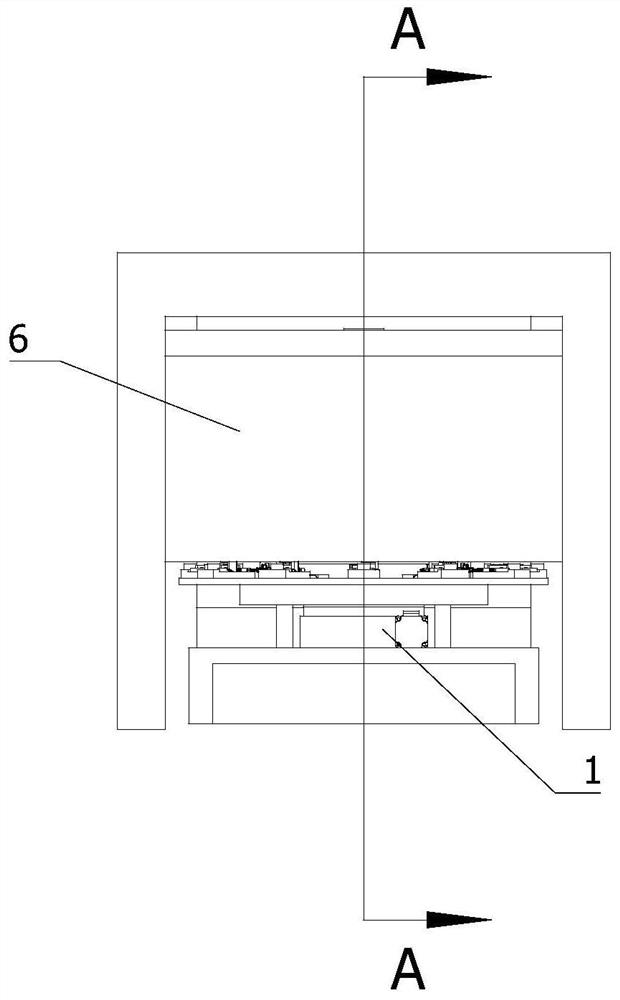
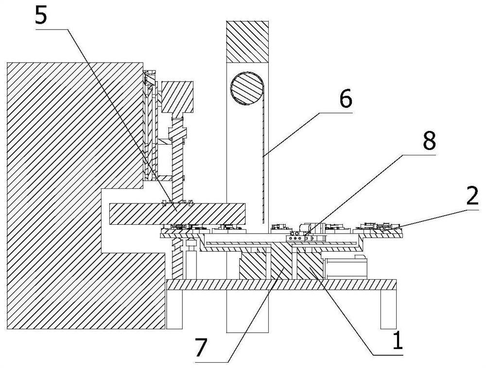
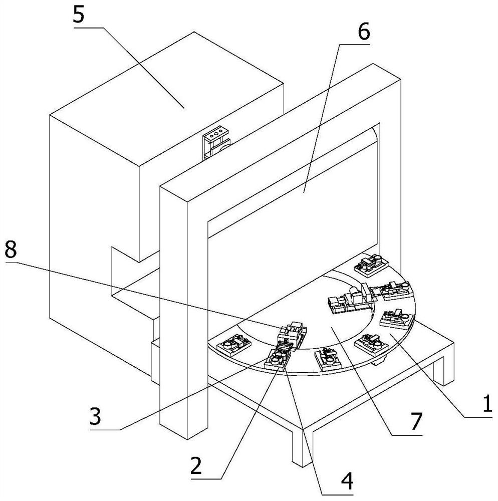
The invention relates to the field of auto parts manufacturing, in particular to a crank connecting rod end surface grinding device, which includes a rotary table, a grinder, and a movable baffle; the table surface of the rotary table is fixedly installed with a plurality of rotary table axis Evenly distributed fixture fixing plates, each fixture fixing plate is fixedly installed with the first workpiece fixture and the second workpiece fixture, the workpiece is placed on the top surface of the fixture fixing plate, and the first workpiece fixture The working end leans against the side of the workpiece, the working end of the second workpiece fixture leans against the top surface of the workpiece, the movable baffle is set directly above the rotary table, and the movable baffle is located at the vertical position where the axis of the rotary table is located. On the surface, the grinding machine is set on one side of the movable baffle, and the working end of the grinding machine is set vertically downward. This equipment can quickly and batch grind the end faces of the crank connecting rods with high efficiency.

Description

technical field [0001] The invention relates to the field of automobile parts manufacturing, in particular to a crank connecting rod end surface grinding device. Background technique [0002] The crank connecting rod mechanism is the main movement mechanism of the engine. Its function is to convert the reciprocating motion of the piston into the rotational motion of the crankshaft, and at the same time convert the force acting on the piston into the torque output by the crankshaft to drive the wheels of the car. The crank connecting rod mechanism is composed of components such as a piston group, a connecting rod group, a crankshaft, and a flywheel group. [0003] After the crank connecting rod is forged, the end faces of the large round end and the small round end need to be polished. At present, the existing equipment can only process the end faces of the crank connecting rod one by one, and cannot process them in batches, so the efficiency is low. Contents of the invent...

Claims


Application Information

Patent Timeline
Patent Type & Authority Patents(China)
IPC IPC(8): B24B7/16B24B41/06B24B55/06B24B27/00B24B41/00
CPCB24B7/16B24B27/0023B24B27/0069B24B41/005B24B41/06B24B55/06
Inventor 富丽慧
Owner 扬州创盟自行车配件有限公司
Learn More