
Intelligent glove pinhole detection device

A detection device and pinhole technology, which can be applied in the direction of measuring the acceleration and deceleration rate of fluids and using liquid/vacuum degree for liquid tightness measurement, etc., can solve the problems of low product inspection efficiency, increased product cost, and increased product cost, etc. To achieve the effect of reducing the risk of unqualified products and improving the accuracy rate

Pending Publication Date: 2020-06-02
SUZHOU COLOR WAY ENTERPRISE DEV
View PDF0 Cites 2 Cited by
  • Summary
  • Abstract
  • Description
  • Claims
  • Application Information

AI Technical Summary

Problems solved by technology

[0003] Manual inspection: At this stage, it is generally used to inflate the product and place it on sensitive parts such as the face or neck, and judge whether the product has air leakage through the human body feeling whether there is air blowing to the part, but the method mainly relies on human senses to detect Judging whether the product has air leakage, each person has a different amount of inflation to the product, and has a different feeling about whether the product is leaking. If you judge carefully, it will easily lead to low product inspection efficiency, and this method is prone to adverse reactions during the product deflation process. The force causes more isolating agent to blow to the face and affect the health of personnel
[0004] Some enterprises use inflatable water inspection method to inflate the product and immerse it in water, and then judge whether the product has holes according to whether there are bubbles coming out. This method has high sensitivity, but the product cost will be increased because the product needs to be re-dried after soaking. , and may produce new damage during the drying process, resulting in a significant increase in product cost

Method used


Image

  • Intelligent glove pinhole detection device
  • Intelligent glove pinhole detection device

Examples


Embodiment Construction

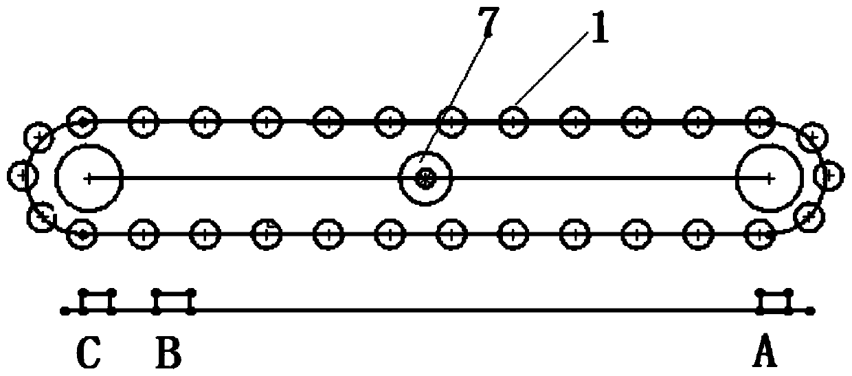
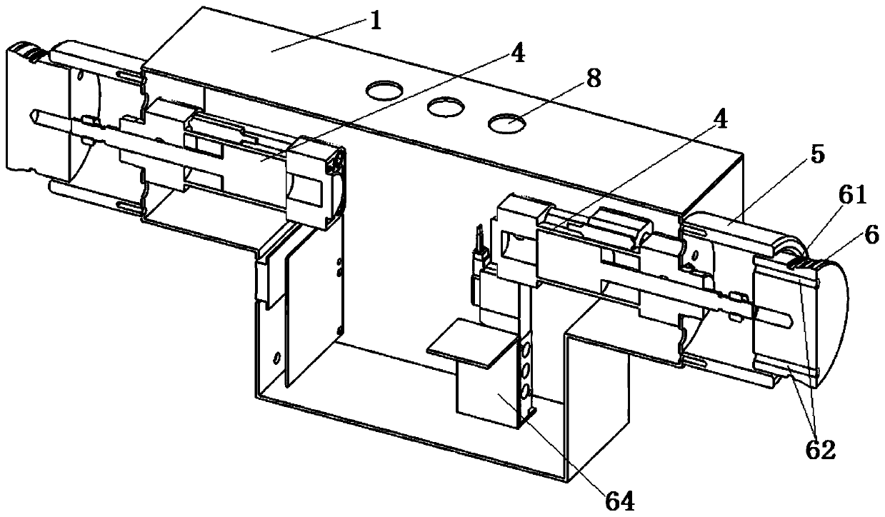
[0017] In view of the above technical solutions, the intelligent detection device for glove pinholes includes: frame, chain, detection head, etc., see Figure 1 to Figure 2 ,in.

[0018] The frame is provided with two rotary chain belts at intervals and parallel intervals on the frame, and several detection devices are arranged at intervals on the two chain belts. The detection head moves and runs under the drive of the chain 1. The chain is arranged on the sprocket, and the sprocket is driven by a motor. The motor is a combination of reducer with deceleration function and speed regulation function. A workbench is arranged on the frame, and the workbench is mainly used for placing the products to be tested and sorting and collecting the tested products. An inflatable position A, a non-conforming product position B, and a qualified product position C are arranged at intervals on the frame below the chain. When the chain drives the detection device to these three positions, ...


PUM


Abstract

The invention discloses an intelligent glove pinhole detection device, and the device comprises a rack and a plurality of detection devices which are sequentially arranged on the rack at intervals. The device is characterized in that each detection device comprises a mounting frame, wherein hollow limiting sleeves are fixedly arranged at the two ends of each mounting frame respectively; each detection device also comprises a detection head and a control device; telescopic detection heads are arranged at the outer ends of the limiting sleeves respectively, and when the detection heads partiallyretract into the limiting sleeves, the limiting sleeves can be sealed with the detection heads making contact with the limiting sleeves; an inflation channel penetrating through the detection head isformed in the detection head, and the inflation device is communicated with the inflation channel; and the control device controls the detection head to act. The detection device can be effectively suitable for hole inspection of different types of glove products, the accuracy of hole inspection is improved, and the risk that the products are unqualified is reduced; performance parameters can beproperly adjusted according to respective product characteristics of enterprises so as to achieve the optimal detection effect.

Description

technical field [0001] The invention relates to glove pinhole detection, in particular to an intelligent pinhole detection device for gloves. Background technique [0002] At present, rubber medical gloves, rubber inspection gloves, PVC gloves, nitrile rubber gloves, rubber household gloves, rubber industrial gloves and other glove inspections basically use compressed air inflation inspection or spot check technology to determine whether the product has holes; the current There are two main inspection processes, one is manual inspection and the other is machine inspection. [0003] Manual inspection: At this stage, it is generally used to inflate the product and place it on sensitive parts such as the face or neck, and judge whether the product has air leakage through the human body feeling whether there is air blowing to the part, but the method mainly relies on human senses to detect Judging whether the product has air leakage, each person has a different amount of inflat...

Claims


Application Information

Patent Timeline
Patent Type & Authority Applications(China)
IPC IPC(8): G01M3/26
CPCG01M3/26
Inventor 周松茂
Owner SUZHOU COLOR WAY ENTERPRISE DEV
Learn More