
Axial flow compressor blade, axial flow compressor and gas turbine

A technology for axial flow compressors and blades, which is applied in the direction of machines/engines, mechanical equipment, liquid fuel engines, etc., can solve problems such as leakage flow, and achieve the effects of weakening leakage vortex strength, reducing losses, and reducing radial clearance

Inactive Publication Date: 2020-06-02
AECC COMML AIRCRAFT ENGINE CO LTD
View PDF17 Cites 6 Cited by
  • Summary
  • Abstract
  • Description
  • Claims
  • Application Information

AI Technical Summary

Problems solved by technology

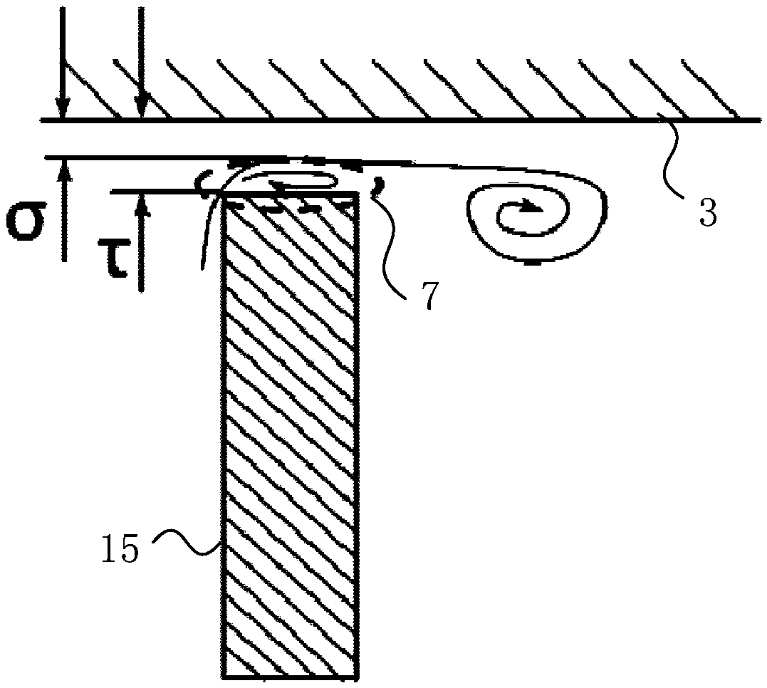
[0003] One of the objectives of the present invention is to provide an axial flow compressor and gas turbine, which can solve the problem of gap leakage flow to a certain extent

Method used


Image

  • Axial flow compressor blade, axial flow compressor and gas turbine
  • Axial flow compressor blade, axial flow compressor and gas turbine
  • Axial flow compressor blade, axial flow compressor and gas turbine

Examples


Embodiment Construction

[0033] The technical solutions in the embodiments of the present invention will be clearly and completely described below in conjunction with the drawings in the embodiments of the present invention. Apparently, the described embodiments are only some of the embodiments of the present invention, not all of them. Based on the embodiments of the present invention, all other embodiments obtained by persons of ordinary skill in the art without creative efforts fall within the protection scope of the present invention.

[0034] In describing the present invention, it is to be understood that the terms "central", "longitudinal", "transverse", "front", "rear", "left", "right", "vertical", "horizontal", The orientations or positional relationships indicated by "top", "bottom", "inner", "outer", etc. are based on the orientations or positional relationships shown in the drawings, and are only for the convenience of describing the present invention and simplifying the description, rathe...


PUM


Abstract

The invention relates to an axial flow compressor blade, an axial flow compressor and a gas turbine. The axial flow air compressor blade comprises a pressure side wall, a blade tip, and a flow guide structure, wherein the flow guide structure is arranged in the area, where the blade tip is located, of the pressure side wall and extends in the chordwise direction of the axial flow compressor blade,and the flow guide structure is used for increasing separation bubbles formed by airflow passing through the flow guide structure on the outer side of the top end face of the blade tip so as to reduce leakage flow at the blade tip. According to the axial flow compressor blade, the axial flow compressor and the gas turbine, the flow guide structure is arranged in the area, where the blade tip is located, of the pressure side wall, so that the shape of the pressure side wall is changed, and a preset angle is formed between the pressure side wall of the axial flow compressor blade and the end face of the top of the blade tip; and gas flows to radial gaps after being guided by the flow guide structure, so that separation bubbles generated by leakage flowing of the gas on the outer side of thetop end face of the blade tip are increased, the effective radial gaps are reduced, the leakage flow is reduced, the leakage vortex strength is weakened, losses caused by gap leakage flowing are reduced, and the performance of the axial flow compressor is improved.

Description

technical field [0001] The invention relates to the field of aviation equipment, in particular to an axial flow compressor blade, an axial flow compressor and a gas turbine. Background technique [0002] Axial flow compressor is the main part of aero-engine and gas turbine, and its efficiency plays a decisive role in the performance of aero-engine. In the axial flow compressor, there is a radial gap between the rotor blade and the casing or between the stator blade and the hub. Under the action of the pressure gradient on both sides of the radial gap of the blade, the gap leakage flow will occur when the gas passes through the radial gap. The interaction between the gap leakage flow and the mainstream in the cascade channel will increase the flow loss and reduce the efficiency of the compressor. Therefore, it is necessary to control the gap leakage flow through some technical means to reduce the loss caused by the leakage flow and improve the efficiency of the compressor. p...

Claims


Application Information

Patent Timeline
IPC IPC(8): F04D29/38F04D29/54F04D29/66
CPCF04D29/384F04D29/388F04D29/544F04D29/667
Inventor 兰云鹤吴帆李游
Owner AECC COMML AIRCRAFT ENGINE CO LTD
Learn More