
Upper expansion sealing device for blow molding equipment

A technology of sealing device and blow molding equipment, which is applied in the field of anti-wrinkle sealing device, which can solve the problems of inability to accurately guarantee the sealing effect, lower yield rate, and easy to flutter.

Pending Publication Date: 2020-06-02
WEIFANG HUAYU PLASTIC MACHINERY
View PDF0 Cites 0 Cited by
  • Summary
  • Abstract
  • Description
  • Claims
  • Application Information

AI Technical Summary

Problems solved by technology

[0003] The existing sealing devices are all arranged under the mold clamping device for sealing the lower end of the tubular blank. This kind of sealing device located below the mold clamping device is called the lower sealing device. The lower sealing device has the following problems : 1. After the tubular blank is extruded from the blank forming die, when the blank reaches a predetermined length, the lower end of the blank is sealed by the lower sealing device, and then placed in the mold opening of the clamping device. After the mold is closed Compressed air is introduced, but due to the fast cooling rate of the tubular blank, when the blank is moved down for sealing and expansion, the shape of the basic material tube has been semi-finalized, which will seriously affect the sealing effect; 2. After the length of the blank reaches the predetermined length , the sealing is carried out, and at this time the billet is long and easy to flutter, and the sealing effect cannot be guaranteed accurately; 3. For some plate-shaped products, the shape of the traditional billet is generally tubular, and the lower end of the billet When sealing, make the bottom end form a flat seal, but when sealing, there is no auxiliary device, and the formed seal will have adhesion wrinkles, and for plate-shaped products such as desktop boards, it has higher requirements for sealing, such as forming adhesions Wrinkles form defective products, reducing yield

Method used


Image

  • Upper expansion sealing device for blow molding equipment
  • Upper expansion sealing device for blow molding equipment
  • Upper expansion sealing device for blow molding equipment

Examples


Embodiment Construction

[0027] Below in conjunction with accompanying drawing and embodiment, further elaborate the present invention. In the following detailed description, certain exemplary embodiments of the invention are described by way of illustration only. Needless to say, those skilled in the art would realize that the described embodiments can be modified in various different ways, all without departing from the spirit and scope of the present invention. Accordingly, the drawings and description are illustrative in nature and not intended to limit the scope of the claims.

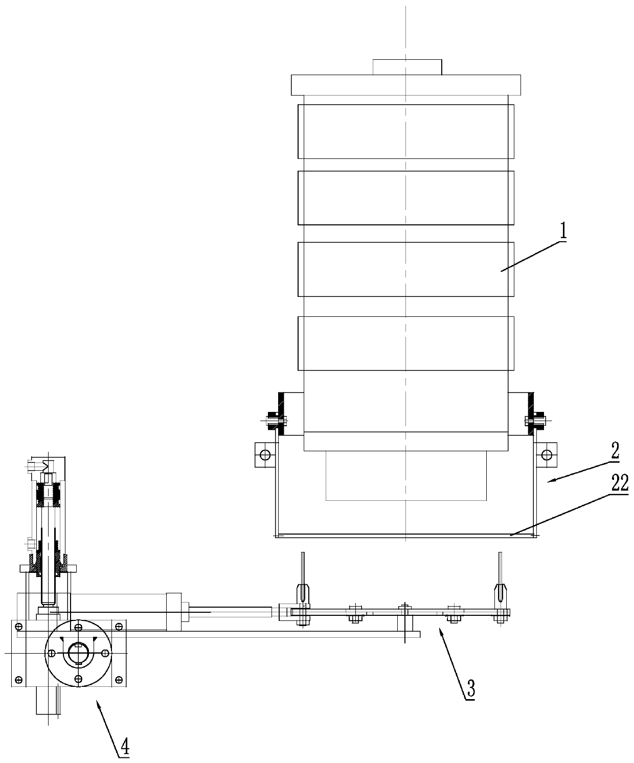
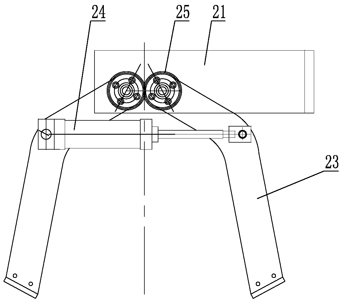
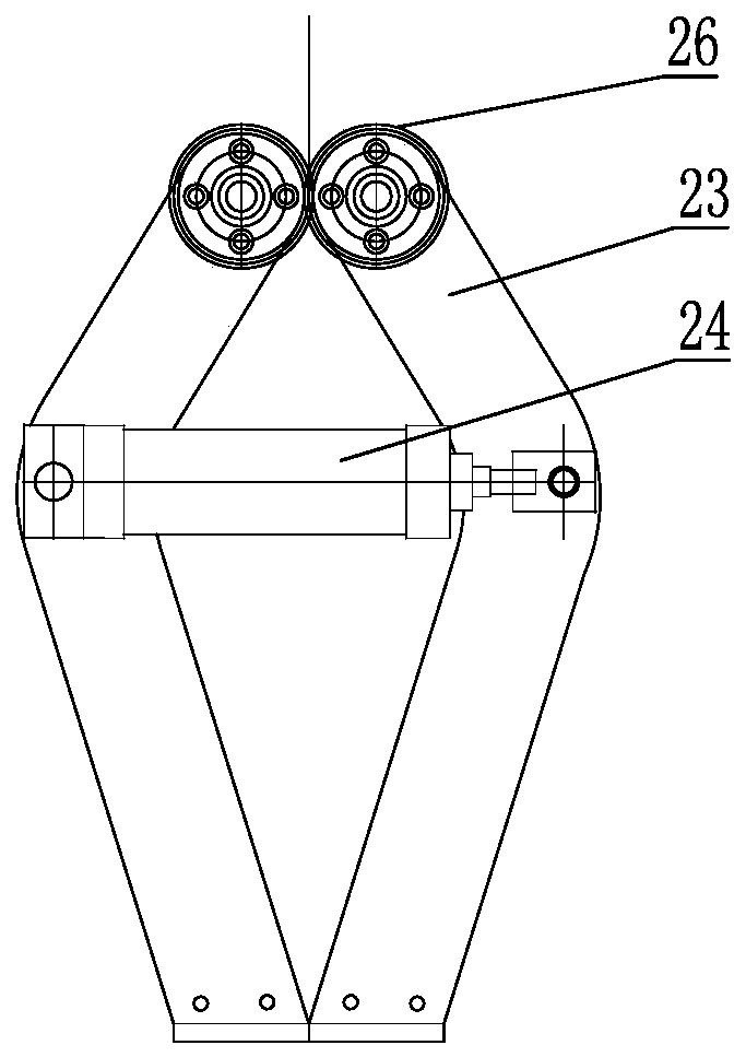
[0028] Such as figure 1 As shown, the blow molding equipment uses an extended sealing device, which is arranged between the blank forming die head 1 and the clamping device. Both the blank forming die head 1 and the clamping device are existing technologies, including the The upper sealing device 2 that opens and closes along the front and rear sides under the blank forming die head 1 is correspondingly provided with a ...


PUM


Abstract

The invention discloses an upper expansion sealing device for blow molding equipment. The upper expansion sealing device is arranged between a material stock forming die head and a mold closing deviceand comprises an upper sealing device which is installed below the material stock forming die head and opens and closes along the front side and the rear side, a material stock expansion device for extending and retracting along the left side and the right side is correspondingly arranged below the upper sealing device, and a material stock avoidance device is further installed at one end of thematerial stock expansion device; when a material stock of the material stock forming die head outpours, the bottom end of the material stock sleeves the material stock expansion device, when the material stock descends a certain height, the material stock expansion device extends in the direction of the left side and the right side, so that the bottom end of the material stock forms a long and thin shape in the left-right direction; and then the upper sealing device closes and clamps the lower end of the material stock from the direction of the left side and the right side, an opening of the lower end of the material stock is sealed, because the material stock is in the long and thin shape in the left-right direction at the moment, meanwhile, sealing is carried out in the direction of theleft side and the right side with the long and thin shape of the material stock, adhesion and wrinkles can be effectively prevented during material stock sealing in the prior art, and the molding rateof products is improved.

Description

technical field [0001] The invention belongs to the technical field of blow molding machines, in particular to an anti-wrinkle sealing device used on large-scale hollow blow molding equipment. Background technique [0002] Blow molding, also known as hollow blow molding, is a rapidly developing plastic processing method. The tubular preform obtained by extruding thermoplastic resin through the extrusion device is placed in the mold opening of the mold clamping device while it is hot or heated to a softened state. After the mold is closed, compressed air is injected into the parison to make the plastic mold The billet is inflated and clings to the inner wall of the mold, and after cooling and demolding, various hollow products can be obtained. [0003] The existing sealing devices are all arranged under the mold clamping device to seal the lower end of the tubular blank. This kind of sealing device located below the mold clamping device is called the lower sealing device. Th...

Claims


Application Information

Patent Timeline
Patent Type & Authority Applications(China)
IPC IPC(8): B29C49/42
CPCB29C49/4273
Inventor 王玉宽李海元周炳宇代成联黄胜利王卫强
Owner WEIFANG HUAYU PLASTIC MACHINERY
Learn More