Method and device used in user equipment and base station for wireless communication
A user equipment and wireless communication technology, applied in wireless communication, radio transmission system, diversity/multi-antenna system, etc., can solve the problem that the licensed spectrum is difficult to meet the demand of business volume, and achieve the effect of efficient management
- Summary
- Abstract
- Description
- Claims
- Application Information
AI Technical Summary
Problems solved by technology
Method used
Image

Examples
Embodiment 1
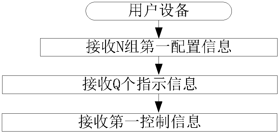
[0124] Embodiment 1 illustrates the flowchart of N sets of first configuration information, Q pieces of indication information and first control information, as shown in the attached figure 1 shown.
[0125]In Embodiment 1, the user equipment in this application receives N sets of first configuration information, and each set of first configuration information in the N sets of first configuration information is used to determine a corresponding set of antenna port groups, The N is a positive integer greater than 1; receiving Q indication information, the Q is a positive integer; receiving first control information, the first control information is associated with first information, and the first information is the Q One of the indication information; wherein, the first information is used to determine the first target configuration information from the N groups of first configuration information; the first target configuration information is the N groups of first A set of fir...
Embodiment 2
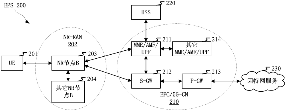
[0214] Embodiment 2 illustrates the schematic diagram of network architecture, as attached figure 2 shown.
[0215] Embodiment 2 illustrates a schematic diagram of a network architecture according to the present application, as attached figure 2 shown. figure 2 It is a diagram illustrating NR 5G, LTE (Long-Term Evolution, long-term evolution) and LTE-A (Long-Term Evolution Advanced, enhanced long-term evolution) system network architecture 200 . The NR 5G or LTE network architecture 200 may be referred to as an EPS (Evolved Packet System, Evolved Packet System) 200 by some other suitable term. EPS 200 may include one or more UE (User Equipment, user equipment) 201, NG-RAN (next generation radio access network) 202, EPC (Evolved Packet Core, evolved packet core) / 5G-CN (5G-Core Network, 5G core network) 210, HSS (Home Subscriber Server, home subscriber server) 220 and Internet service 230. The EPS may be interconnected with other access networks, but these entities / interf...
Embodiment 3
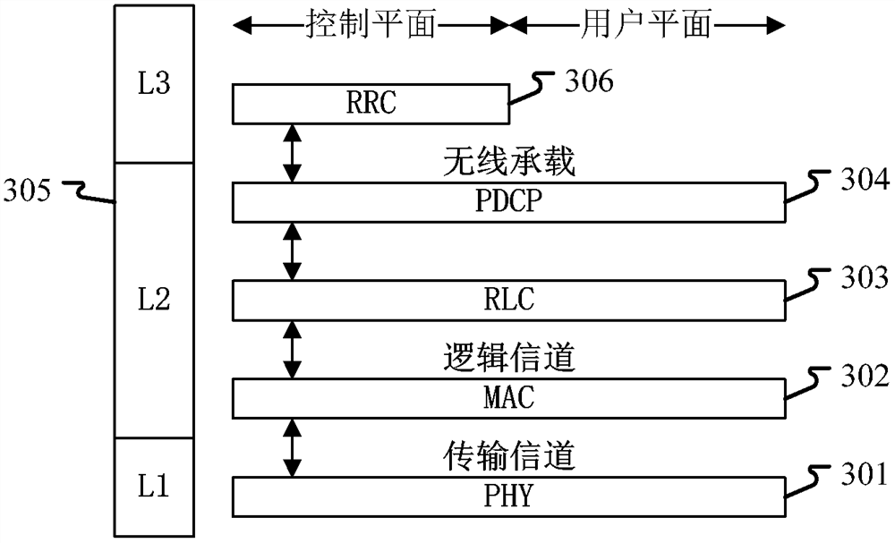
[0223] Embodiment 3 shows a schematic diagram of an embodiment of a wireless protocol architecture of a user plane and a control plane according to the present application, as shown in the attached image 3 shown.
[0224] attached image 3 is a schematic diagram illustrating an embodiment of a radio protocol architecture for a user plane and a control plane, image 3 The radio protocol architecture for user equipment (UE) and base station equipment (gNB or eNB) is shown in three layers: layer 1, layer 2 and layer 3. Layer 1 (L1 layer) is the lowest layer and implements various PHY (Physical Layer) signal processing functions. The L1 layer will be referred to herein as PHY 301 . Layer 2 (L2 Layer) 305 is above PHY 301 and is responsible for the link between UE and gNB through PHY 301 . In the user plane, the L2 layer 305 includes MAC (Medium Access Control, Media Access Control) sublayer 302, RLC (Radio LinkControl, Radio Link Layer Control Protocol) sublayer 303 and PDCP ...
PUM
 Abstract
Description
Claims
Application Information
 - Generate Ideas
- Intellectual Property
- Life Sciences
- Materials
- Tech Scout
- Unparalleled Data Quality
- Higher Quality Content
- 60% Fewer Hallucinations
Browse by: Latest US Patents, China's latest patents, Technical Efficacy Thesaurus, Application Domain, Technology Topic, Popular Technical Reports.
© 2025 PatSnap. All rights reserved.Legal|Privacy policy|Modern Slavery Act Transparency Statement|Sitemap|About US| Contact US: help@patsnap.com