Eureka AIR delivers breakthrough ideas for toughest innovation challenges, trusted by R&D personnel around the world.

Electrical cabinet with smoke-sensing cooling and dehumidifying device

A technology for cooling and dehumidification, electrical cabinets, applied in the field of electrical cabinets, can solve the problems of electrical cabinet surface corrosion, fire prone, electrical cabinet damage, etc., to avoid corrosion, avoid fire, and reduce losses.

Inactive Publication Date: 2020-05-29
柴宣何
View PDF9 Cites 2 Cited by
  • Summary
  • Abstract
  • Description
  • Claims
  • Application Information

AI Technical Summary

Problems solved by technology

For this reason, an object of the present invention is to provide an electrical cabinet with a smoke sensor cooling and dehumidification device, which is mainly used to solve the problem that when the existing electrical cabinet is used, heat will be generated, and after the heat is accumulated, it is easy to catch fire, which will make the entire electrical cabinet The cabinet is damaged, causing serious losses. At the same time, the electrical cabinet may be placed in a humid environment, and the surface of the metal electrical cabinet is easily corroded due to environmental influences.

Method used


Image

  • Electrical cabinet with smoke-sensing cooling and dehumidifying device
  • Electrical cabinet with smoke-sensing cooling and dehumidifying device
  • Electrical cabinet with smoke-sensing cooling and dehumidifying device

Examples


Embodiment 1

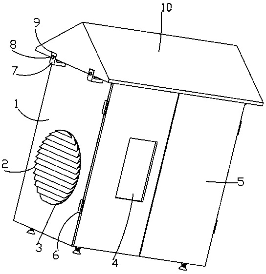
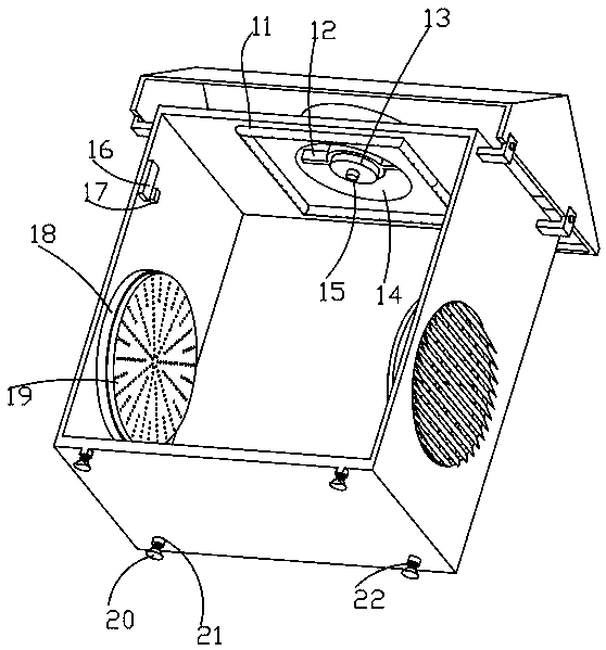
[0033] like Figure 1-6An electrical cabinet with a smoke cooling and dehumidification device is shown, including an electrical cabinet, a fan 13, a smoke generator 15, a controller 16, and a protection switch 17. The bottom of the electrical cabinet 1 is symmetrically provided with an adjustable support structure, and the adjustable support structure It includes spacer 20, threaded post 22 and bushing 21, the bottom of bushing 21 is fixedly connected with electrical cabinet 1, the bottom of bushing 21 is threadedly connected with threaded post 22 through thread groove, and the bottom of threaded post 22 is fixedly connected with spacer 20, through The threaded column 22 in the adjustable support structure is connected with the casing thread 21, which is convenient to drive the pad 20 to adjust the position, and is convenient to adjust the horizontal state of the device. The 3 places are fixedly connected with the rain-shielding inclined plate 2 sequentially from top to bottom...

Embodiment 2

[0035] like Figure 1-6 As shown, an electrical cabinet with a smoke sensor cooling and dehumidification device includes an electrical cabinet, a fan 13, a smoke generator 15, a controller 16, and a protection switch 17. The bottom of the electrical cabinet 1 is symmetrically provided with an adjustable support structure, and the electrical cabinet 1 is left and right The outer wall is provided with a vent hole 3, and the electrical cabinet 1 is fixedly connected with a rain-shielding slope plate 2 from top to bottom at the vent hole 3, and the electrical cabinet 1 is fixedly connected with a threaded sleeve 29 at the inner wall of the vent hole 3, and the threaded sleeve 29 passes the thread The groove is threadedly connected with a circular partition 18, and the circular partition 18 is connected with a desiccant placement plate 19 filled with a desiccant through a threaded groove, and the side walls of the circular partition 18 and the desiccant placement plate 19 are evenly...

Embodiment 3

[0037] like Figure 1-6 As shown, an electrical cabinet with a smoke sensor cooling and dehumidification device includes an electrical cabinet, a fan 13, a smoke generator 15, a controller 16, and a protection switch 17. The bottom of the electrical cabinet 1 is symmetrically provided with an adjustable support structure, and the electrical cabinet 1 is left and right The outer wall is provided with a vent hole 3, and the electrical cabinet 1 is fixedly connected with a rain-shielding slope plate 2 from top to bottom at the vent hole 3, and the electrical cabinet 1 is fixedly connected with a threaded sleeve 29 at the inner wall of the vent hole 3, and the threaded sleeve 29 passes the thread The groove is threadedly connected with a circular partition 18, and the circular partition 18 is connected with a desiccant placement plate 19 filled with a desiccant through a threaded groove, and the side walls of the circular partition 18 and the desiccant placement plate 19 are evenly...


PUM


Abstract

The invention relates to an electrical cabinet with a smoke-sensing cooling and dehumidifying device in the field of electrical equipment. An electrical cabinet is included, and the electrical cabinetis provided with an adjustable supporting structure. An air vent is arranged on the electrical cabinet, and the electrical cabinet is provided with a rain-shielding inclined plate; the electrical cabinet is provided with a threaded sleeve, the threaded sleeve is connected with a circular partition plate; the circular partition plate is provided with a drying agent placing disc filled with a drying agent; through holes are uniformly arranged in side walls of the circular partition plate and the drying agent placing disc; the electrical cabinet is provided with a controller and a protection switch; a straight hole is arranged on the electrical cabinet, the straight hole is provided with a mounting rack, a fan is arranged on the mounting rack, an aerosolizer is arranged on the fan, a fire extinguishing structure is arranged on the electrical cabinet, and the electrical cabinet is provided with a movable installation structure; the movable installation structure is provided with a cabinettop; and the electrical cabinet is provided with a hinge, and the hinge is fixedly connected with a door plate. The electrical cabinet is helpful for reducing a temperature of electrical components in the electrical cabinet, a possibility of fire disasters is avoided, the electrical cabinet is well protected and losses are reduced, and meanwhile, corrosion of damp air to the electrical cabinet made of metal and the electrical components in the electrical cabinet can be avoided, and a service life of equipment is prolonged.

Description

technical field [0001] The invention relates to the field of electrical equipment, in particular to an electrical cabinet with a smoke detector cooling and dehumidifying device. Background technique [0002] The electrical cabinet is also called the power distribution cabinet. The power distribution cabinet is divided into the power distribution cabinet, the lighting distribution cabinet, and the metering cabinet. It is the final equipment of the power distribution system. The power distribution cabinet is a general term for the motor control center. The power distribution cabinet is used in the occasions where the load is relatively scattered and there are few circuits; the motor control center is used in the occasions where the load is concentrated and there are many circuits. They distribute the electric energy of a certain circuit of the upper-level power distribution equipment to the nearest load. This level of equipment shall provide protection, monitoring and contro...

Claims


Application Information

Patent Timeline
Patent Type & Authority Applications(China)
IPC IPC(8): H02B1/30H02B1/56H02B1/28A62C37/42
CPCA62C37/42H02B1/28H02B1/30H02B1/565
Inventor 柴宣何陈伟
Owner 柴宣何
Why Eureka
Eureka Blog
Learn More