Electronic detonator leg wire tail end connecting device and blasting system and application thereof

A technology of electronic detonators and connection devices, which is applied in the direction of weapon accessories, fuzes, offensive equipment, etc., and can solve the problems of inability to realize the shape of the blasting and directional blasting, the shape of the blasting, the target of the blasting orientation, and unreliable connections. , to achieve the effect of maintaining integrity and stability, good water and rain resistance, and ensuring precise controllability

Inactive Publication Date: 2020-05-29
谢正怀
View PDF0 Cites 1 Cited by
  • Summary
  • Abstract
  • Description
  • Claims
  • Application Information

AI Technical Summary

Problems solved by technology

like figure 1 As shown, in the current electronic detonator blasting system, the tail wires of each electronic detonator are connected to the detonating bus in parallel, and the connection and installation are completed through junction boxes. Usually, several junction boxes are clamped on the detonating bus, and The detonating busbars are all metal wires such as copper core wires. During installation, the skin needs to be peeled off manually to ensure that the cutter touches the copper core wires, and then the detonator and the detonating busbars are wound together. If the exposed wire is in contact with the ground or in rainy weather, it will easily cause excessive network resistance or short circuit, which will affect the detonation network, and it is time-consuming and labor-intensive to connect multiple groups of detonator legs to the detonation bus, which greatly reduces improved work efficiency
[0003] In order to achieve the shape of the set blasting and directional blasting, adjacent blasting holes must be equipped with detonators of different sections and detonated sequentially after being connected to the network one by one with a delay, and the detonators of different sections can only be detonated at the same time. When the detonation signal is received, each detonator must be disconnected from the connected blasting network at the moment when the detonation signal is received, otherwise the hole that explodes first will pull out and displace the unexploded detonator in the adjacent hole due to the delay , resulting in failure to achieve the set blasting shape and blasting orientation goals;
[0004] However, the current connection device for connecting the electronic detonator to the blasting network is that the metal wire is very firmly connected and cannot be disconnected after receiving the detonation signal, which will cause the impact force of the first blast hole to pass through the metal network connection wire or the connecting piece that cannot be easily detached. Drag and displace the unexploded detonators in the adjacent holes due to delay, so that the shape of the blasting and the goal of directional blasting cannot be achieved; in addition, after the blasting network is formed, the detonation signal of the electronic detonator is transmitted to the For each digital electronic detonator, the circuit of the detonation network must be unblocked, but the current connection device of the blasting network of the electronic detonator is not waterproof. Many digital electronic detonators cannot receive the detonation signal and become blind shots, which leads to the inability to achieve the set blasting shape and directional blasting goals

Method used


Image

  • Electronic detonator leg wire tail end connecting device and blasting system and application thereof
  • Electronic detonator leg wire tail end connecting device and blasting system and application thereof
  • Electronic detonator leg wire tail end connecting device and blasting system and application thereof

Examples


Embodiment 1

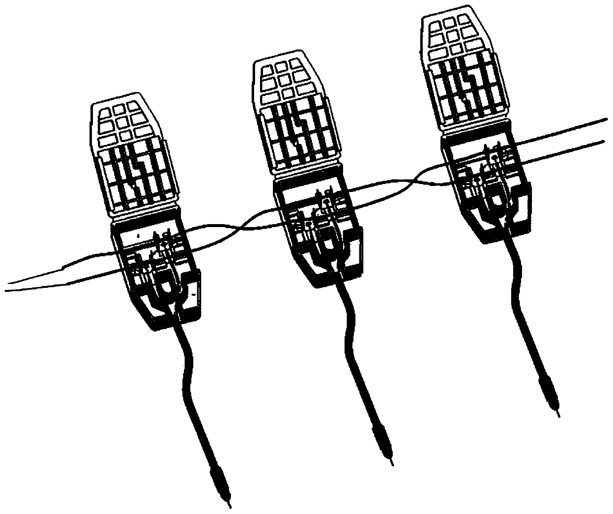
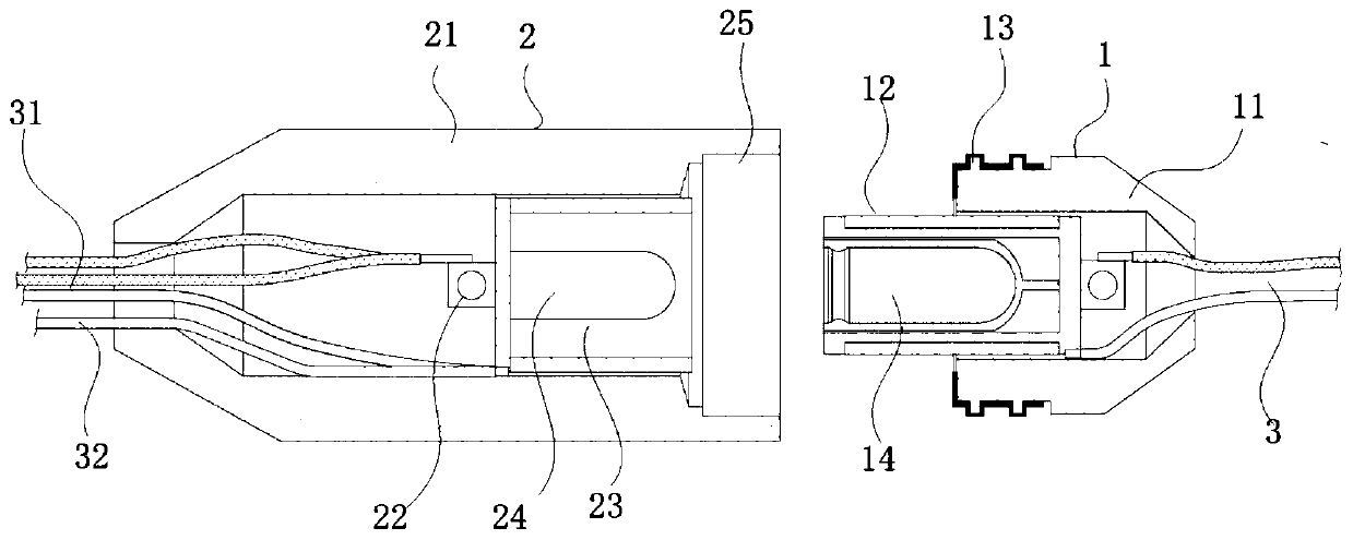
[0036] Embodiment 1: as figure 2 , 3As shown in , 4, the connecting device at the end of the electronic detonator foot wire includes two sections of detachable male-female butt joints that are mutually detachable. Connecting parts, the male plug-in 1 and the female plug-in 2 can conduct a circuit after being plugged and connected, the male plug-in 1 is connected to the detonating bus 3, and the female plug-in 2 is connected to another section of the detonating bus 3 and the detonator foot wire 4, Both the male plug 1 and the female plug are integrally formed adapters, and the interior is sealed and waterproof after docking. One end of the detonating busbar 3 is connected to the detonator, and the rest of the detonating busbar 3 is divided into several sections and connected between the female plug-in 2 and the male plug-in 1 in turn to form a complete detonating busbar 3. One parallel connection is connected to each electronic detonator, and the electronic detonator is conn...

Embodiment 2

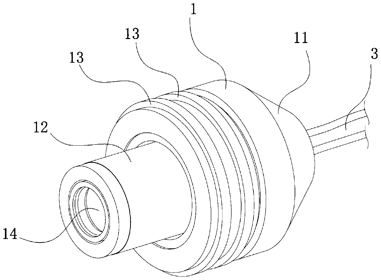
[0037] Embodiment 2: on the basis of embodiment 1, as Figure 2-4 , Figure 7 , 8 As shown, preferably, the easy-to-fall male and female butt connectors are integrally formed as a front and rear two-way tubular body, the male connector 1 includes a plug body 11 and a protruding head 12, and the female connector 2 includes a female plug body 21, placed The line electrode 22 and the groove part 23 in the female plug body 21, the protruding head 12 and the groove part 23 are matched, and at least one Circle waterproof ring 13. In actual use, hold the plug body 11, align the convex head 12 with the groove 23 on the female plug body 21 of the female plug 2, insert the convex head 12 into the groove 23, and the male and female plugs 2 are docked Finish. The rear end of the plug body 11 is connected to the detonating busbar 3 , and the line electrode 22 is connected to another section of the detonating busbar 3 and a section of detonator foot wire 4 and connected to the tail of t...

Embodiment 3

[0039] Embodiment 3: on the basis of embodiment 1,2, as Figure 5 , 6 As shown in , 9, the easy-to-fall off male-female butt connectors are generally a three-way tubular body molded from PVC material, and the bifurcation section 5 is arranged on the tail side of the female plug body 21 and extends vertically to connect to the line inside the female plug body 21 The detonator leg 4 of the electrode 22 is connected to the electronic detonator through the branch section 5 . The bifurcation section 5 and the female plug body 21 form a vertical right-angle section, which is used for arranging the leg line 4 of the detonator, which is separated from the detonating busbar 3 and can improve installation efficiency.


PUM


Abstract

The invention discloses an electronic detonator leg wire tail end connecting device and a blasting system and application to the electronic detonator leg wire tail end connecting device. The electronic detonator leg wire tail end connecting device comprises two sections of easy-to-fall male and female butt joint connectors which are mutually detachable, the easy-to-fall male and female butt jointconnectors comprise a male plug-in and a female plug-in without a locking connecting part, the male plug-in and female plug-in can conduct circuit after being connected in inserted mode, wherein the male plug-in unit is connected to a detonation bus, the female plug-in unit is connected to another section of detonation bus and a detonator leg wire, and the interior of the female plug-in unit is sealed and waterproof after butt joint.The male plug-in unit and the female plug-in unit are molded by adopting a PVC (Polyvinyl Chloride) material, can ensure parallel circuit connection and are easy to fall off when encountering micro external force; the explosion refusing phenomenon caused by the two problems that the sequential detonation of the adjacent electronic detonators is influenced and needs to be disconnected in time but the metal wire connection cannot be disconnected and the connection circuit of the non-waterproof junction box encounters water and is short-circuited due to the delay difference of the existing electronic detonator leg wire connection device is fundamentally overcome; therefore, the set blasting shape and the directional blasting purpose can be achieved.

Description

technical field [0001] The invention relates to the technical field of detonator blasting, in particular to an electronic detonator foot wire end connection device and its applied blasting system and application. Background technique [0002] Electronic detonators, also known as digital electronic detonators, digital detonators or industrial digital electronic detonators, are electric detonators that use electronic control modules to control the detonation process. Such as figure 1 As shown, in the current electronic detonator blasting system, the tail wires of each electronic detonator are connected in parallel to the detonating bus, and the connection and installation are completed through junction boxes. Usually, several junction boxes are clamped on the detonating bus, and The detonating busbars are all metal wires such as copper core wires. During installation, the skin needs to be peeled off manually to ensure that the cutter touches the copper core wires, and then th...

Claims


Application Information

Patent Timeline
Patent Type & Authority Applications(China)
IPC IPC(8): F42C19/12
CPCF42C19/12
Inventor 谢正怀
Owner 谢正怀
Why Eureka
Try Eureka