Cascade energy-storage type air source heat pump direct-condensation floor heating system

An air source heat pump, direct condensing technology, applied in heating systems, heating methods, heat storage equipment, etc., can solve the problems of low energy storage density of storage water tanks, reduce operating costs, occupy indoor space, etc., and save heat storage. The effect of water tank space, reducing power consumption and prolonging heat release time

Inactive Publication Date: 2020-05-29
TIANJIN UNIV
View PDF12 Cites 2 Cited by
  • Summary
  • Abstract
  • Description
  • Claims
  • Application Information

AI Technical Summary

Problems solved by technology

However, the system has the following problems question : 1) The energy storage density of the storage water tank used in the system is low. If the water tank is small in size, it cannot store enough heat to meet the heating and defrosting requirements of the system. If the volume of the device is too large, it will occupy the indoor space; 2) In thermal mode, it is necessary to consume high-grade energy (electric energy) to drive the heat pump cycle in order to prepare high-temperature and high-pressure refrigerant for heat storage in the water storage tank. It can only be used for refrigerant evaporation and heat absorption, and it needs to work through the compressor to be used for indoor heating. It is not energy-saving, and it still needs to consume electric energy during the daytime peak power period to drive the heat pump cycle to provide heating, so it cannot effectively reduce operating costs.

Method used


Image

  • Cascade energy-storage type air source heat pump direct-condensation floor heating system
  • Cascade energy-storage type air source heat pump direct-condensation floor heating system

Examples


Embodiment Construction

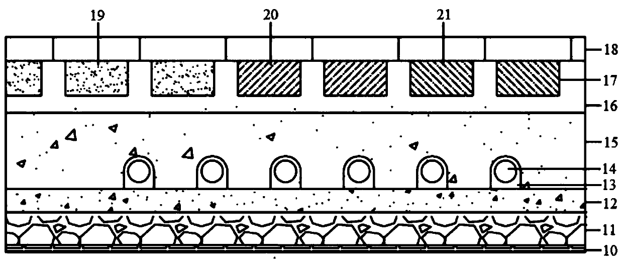
[0022] The technical solutions of the present invention will be clearly and completely described below in conjunction with the accompanying drawings and embodiments.

[0023] Such as figure 1 Shown is a structural schematic diagram of a cascaded energy storage type air source heat pump direct-condensing floor heating system of the present invention. The system includes an evaporator 1 , a four-way reversing valve 2 , a gas-liquid separator 3 , a compressor 4 , a solenoid valve 5 , a cascade phase change floor 6 , a liquid reservoir 7 , a filter 8 and an expansion valve 9 . Wherein, the input end of the compressor 4 communicates with the output end of the gas-liquid separator 3 . Both sides of the input and output ends of the expansion valve 9 are provided with filters 8 to ensure that the air source heat pump can prevent impurities from entering the compressor no matter it is in the heating or defrosting mode. The four ports of the four-way reversing valve 2 communicate wit...


PUM

PropertyMeasurementUnit
Phase transition temperatureaaaaaaaaaa

Abstract

The invention discloses a cascade energy-storage type air source heat pump direct-condensation floor heating system, which comprises an evaporator (1), a four-way reversing valve (2), a gas-liquid separator (3), a compressor (4), a solenoid valve (5), a cascade phase change floor (6), a liquid storage device (7), a filter (8) and an expansion valve (9), wherein a cascade energy-storage structure is arranged in the cascade phase change floor (6), and heat is stored in the cascade phase change floor (6). Compared with the prior art, the cascade energy-storage type air source heat pump direct-condensation floor heating system can save the space of a heat storage water tank, in addition, stored heat can be directly used for heat supply, a heat pump does not need to be started, the electricityconsumption and the operation cost of the system during a daytime peak electricity period can be effectively lowered. The utilization of the cascade phase change floor can realize cascade heat storage, a heat storage rate is improved, the heat releasing time of a phase change material can be prolonged, and heat can be slowly released so as to be favorable for indoor thermal comfort.

Description

technical field [0001] The invention relates to the technical field of residential heating systems, in particular to an air source heat pump direct-condensing floor heating system. Background technique [0002] The air source heat pump direct condensation floor radiant heating system is a new heating method, which couples the air source heat pump technology with the refrigerant direct floor radiant heating technology. It has the advantages of good thermal comfort, low energy consumption, and high energy efficiency. It has broad application prospects. . However, there are still some problems in the application process of the air source heat pump direct condensation floor radiation heating system, which limits its further promotion. First of all, during the defrosting process of the air source heat pump, the refrigerant in the heating pipe of the floor heating will cause the temperature of the floor to drop, which will reduce the thermal comfort of the room; Compared with th...

Claims


Application Information

Patent Timeline
IPC IPC(8): F24D11/02F24D19/10F28D20/02
CPCF24D11/0214F24D19/1039F28D20/02Y02B30/12Y02E60/14
Inventor 吕石磊许勃文
Owner TIANJIN UNIV
Why Eureka
Try Eureka