
Crawler-type water getting device

A water intake device and crawler type technology, applied in the field of crawler water intake device, can solve the problems of lack of walking power, mobility, poor flexibility, impossibility and other problems

Pending Publication Date: 2020-05-29
JIEDA FIRE PROTECTION VEHICLE EQUIP CO LTD SUZHOU CITY
View PDF5 Cites 0 Cited by
  • Summary
  • Abstract
  • Description
  • Claims
  • Application Information

AI Technical Summary

Problems solved by technology

The technical information of various water intake devices can be seen in the published Chinese patent documents, such as the "water intake device" recommended by CN106730540A. However, there are still the following shortcomings: first, because it does not have the driving power, it needs to rely on the additionally equipped front traction, so on the one hand, the volume is significantly increased, and on the other hand, the Manufacturing costs; second, because they cannot walk on their own, their mobility and flexibility are poor. For example, when drainage is to be implemented, they cannot get as close as possible to the drainage site and it is difficult to park at the drainage site; third, due to the use of wheeled Walking, so it is picky about special road conditions, such as snow, hillside, soft, muddy, grass and other terrains that are difficult or even impossible to pass

Method used


Image

  • Crawler-type water getting device
  • Crawler-type water getting device
  • Crawler-type water getting device

Examples


Embodiment Construction

[0020] In order to be able to understand the technical essence and beneficial effects of the present invention more clearly, the applicant will describe in detail in the form of examples below, but the description of the examples is not a limitation to the solution of the present invention. Anything made according to the concept of the present invention All equivalent transformations that are merely formal rather than substantive should be regarded as the scope of the technical solution of the present invention.

[0021] In the following description, all concepts related to the directionality or orientation of up, down, left, right, front and rear are based on figure 1 The position state shown is a reference, so it cannot be understood as a special limitation to the technical solution provided by the present invention.

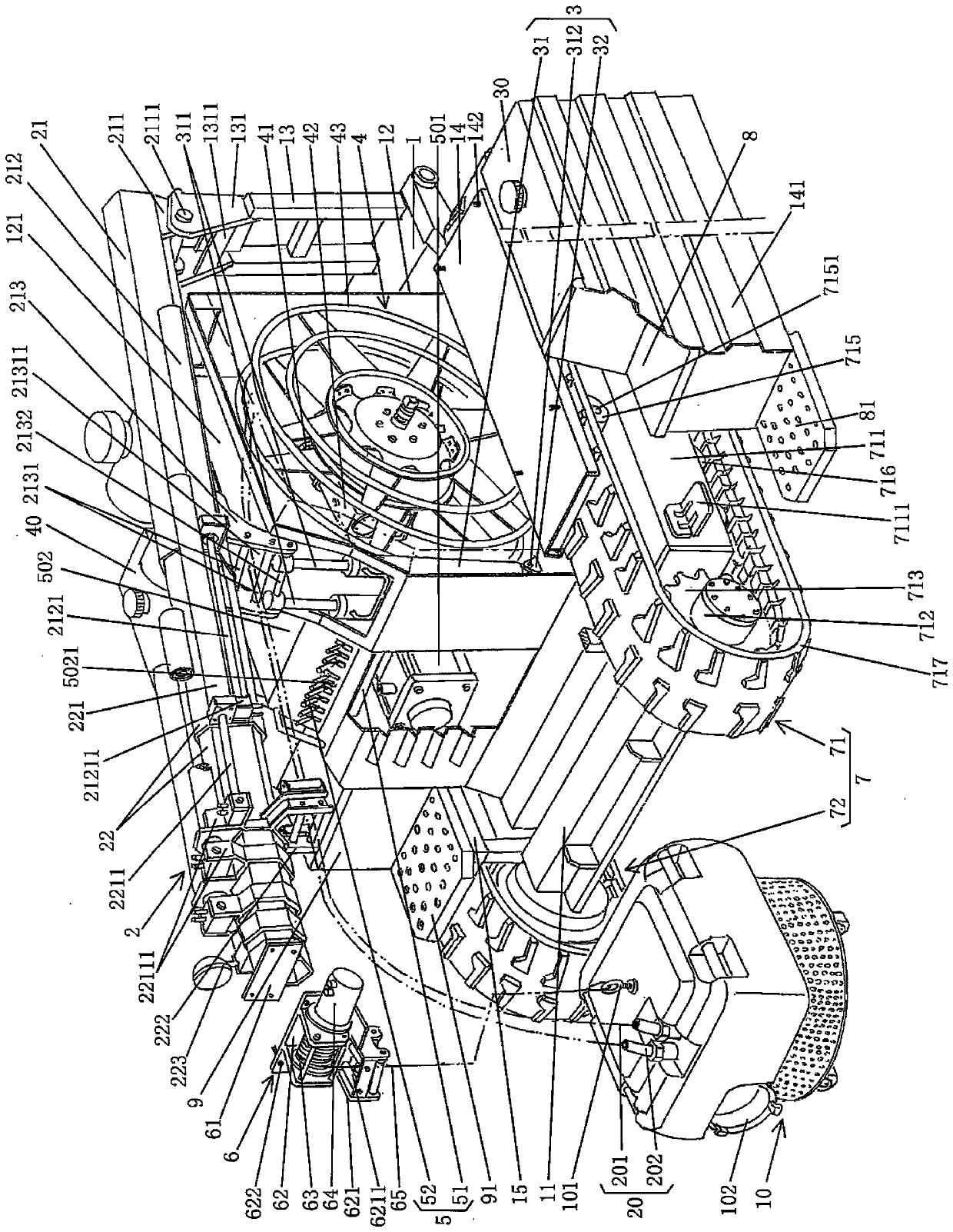
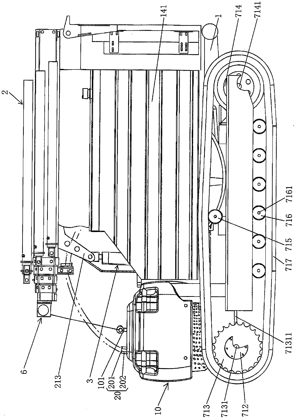
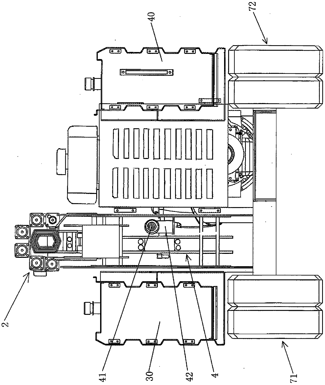
[0022] See figure 1 , Shows a frame chassis 1; a telescopic boom mechanism 2, one end of the telescopic boom mechanism 2 is hinged to the right end of the chassis c...


PUM


Abstract

The invention provides a crawler-type water getting device and belongs to the technical field of disaster relief facilities. The crawler-type water getting device comprises a rack chassis, a telescopic jib mechanism, a jib lift driving mechanism, a water getting pump working oil pipe winding and unwinding mechanism, a water getting pump, a water getting pump working oil pipe, a water getting pumphoisting mechanism, a crawler walking mechanism, an engine oil supply box, a hydraulic oil tank, an engine and a hydraulic operation control mechanism, wherein one end of the telescopic jib mechanismis hinged with the right end of the rack chassis, and the other end stretches toward the left end of the rack chassis; the lower part of the jib lift driving mechanism is connected with the rack chassis, and the upper part is connected with the telescopic jib mechanism; the water getting pump working oil pipe winding and unwinding mechanism is arranged on the rack chassis; the water getting pump is placed on the rack chassis; one end of the water getting pump working oil pipe is connected to the water getting pump working oil pipe winding and unwinding mechanism, and the other end is connectedwith the water getting pump; the water getting pump hoisting mechanism is connected with the water getting pump; the crawler walking mechanism is used for driving the rack chassis to walk; the engineoil supply box, the hydraulic oil tank and the engine are arranged on the rack chassis; the left side of the engine is correspondingly provided with a hydraulic oil pump; the hydraulic oil pump is connected with the engine; and the hydraulic operation control mechanism is arranged in accompany with the engine. The crawler-type water getting device reduces the size, lowers the manufacturing cost,guarantees a flood drainage effect and can meet the requirement of not needing specified road conditions.

Description

Technical field [0001] The invention belongs to the technical field of disaster relief facilities, and specifically relates to a crawler-type water intake device. Background technique [0002] The aforementioned water intake device is mainly used for draining and drawing water, but it is not absolutely limited to draining and drawing water. For example, the fire truck can be provided with water for fire fighting through a hose. The technical information of various water extraction devices can be seen in the published Chinese patent documents, such as the "water extraction device" recommended by CN106730540A. This patent summarizes four common occasions of water extraction devices and can faithfully reflect the technical effect column of the specification. The two aspects of technical effects recorded in the document, but there are still the following shortcomings: First, because it does not have the driving power of its own, it needs to rely on separately equipped front traction,...

Claims


Application Information

Patent Timeline
IPC IPC(8): E03B5/00E03F5/22B62D55/06A62C31/00A62C31/28
CPCE03B5/00E03F5/22B62D55/06A62C31/00A62C31/28Y02A20/20
Inventor 张建明
Owner JIEDA FIRE PROTECTION VEHICLE EQUIP CO LTD SUZHOU CITY
Learn More