
Phase compensation circuit and method and operational amplifier

A phase compensation and amplifier circuit technology, used in high-frequency amplifiers, power amplifiers, improving amplifiers to reduce nonlinear distortion, etc., can solve the problems of radio frequency performance deterioration, low closed-loop phase compensation accuracy, etc. Effect of circuit phase margin and stability

Pending Publication Date: 2020-05-26
SHENNAN CIRCUITS
View PDF0 Cites 0 Cited by
  • Summary
  • Abstract
  • Description
  • Claims
  • Application Information

AI Technical Summary

Problems solved by technology

[0004] The application provides a phase compensation circuit, method and operational amplifier, which can solve the problems of low precision of closed-loop phase compensation and deterioration of radio frequency performance in the prior art

Method used


Image

  • Phase compensation circuit and method and operational amplifier
  • Phase compensation circuit and method and operational amplifier
  • Phase compensation circuit and method and operational amplifier

Examples


Embodiment Construction

[0017] The following will clearly and completely describe the technical solutions in the embodiments of the present application with reference to the accompanying drawings in the embodiments of the present application. Obviously, the described embodiments are only part of the embodiments of the present application, not all of them. Based on the embodiments in this application, all other embodiments obtained by persons of ordinary skill in the art without making creative efforts belong to the scope of protection of this application.

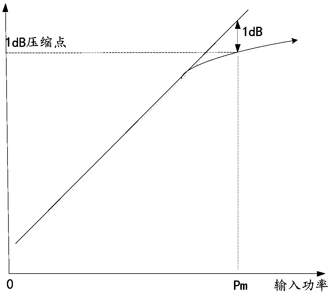
[0018] Operational amplifiers are generally used to amplify the power of radio frequency signals output by radio frequency circuits. combine figure 2 , figure 2 It is the curve characteristic diagram of the input / output power of the amplifier circuit of this application. like figure 2 As shown, the op amp circuit has a linear dynamic range as figure 2 The power of the input radio frequency signal shown is in the range of [0, Pm], the power...


PUM


Abstract

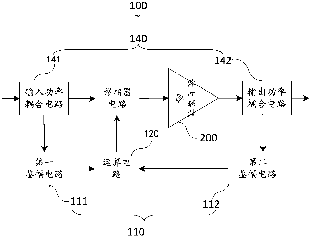
The invention discloses a phase compensation circuit and method and an operational amplifier. The phase compensation circuit comprises an amplitude discriminator unit, an operational circuit and a phase shifter circuit. The amplitude discriminator unit is used for extracting amplitude information of an input signal and an output signal of the amplifier circuit and sending the amplitude informationto the operational circuit to obtain a first phase compensation voltage of the amplifier circuit, and the phase shifter circuit performs phase compensation on the output signal of the amplifier circuit according to the first phase compensation voltage. By means of the mode, the loop phase allowance and stability can be improved, and the compensation precision of closed-loop phase compensation isimproved.

Description

technical field [0001] The present application relates to the technical field of operational amplifier phase compensation, in particular to a phase compensation circuit, method and operational amplifier. Background technique [0002] With the evolution of modern wireless communication towards high-speed and large-capacity, users' requirements for broadband communication are constantly increasing, and the next-generation technology is becoming more and more demanding on the performance of radio frequency and microwave operational amplifiers. RF operational amplifiers have similar technical characteristics. , requiring lower signal distortion and higher signal peak-to-average power ratio. [0003] At the same time, a problem that has to be faced is that the RF operational amplifier is essentially a nonlinear device, which will produce unwanted intermodulation distortion products, which will directly affect the quality of the RF signal. The distortion introduced by the RF ampl...

Claims


Application Information

Patent Timeline
IPC IPC(8): H03F1/32H03F3/189H03F3/20
CPCH03F1/32H03F3/189H03F3/20Y02D30/70
Inventor 潘松钟名庆
Owner SHENNAN CIRCUITS
Learn More