Eureka AIR delivers breakthrough ideas for toughest innovation challenges, trusted by R&D personnel around the world.

Accurate positioning method of tooling plate

A precise positioning and tooling board technology, applied in image data processing, instruments, calculations, etc., can solve the problem of poor positioning accuracy and cannot meet high-precision positioning requirements, and achieve the effect of improving positioning accuracy.

Pending Publication Date: 2020-05-26
JIHUA LAB
View PDF5 Cites 4 Cited by
  • Summary
  • Abstract
  • Description
  • Claims
  • Application Information

AI Technical Summary

Problems solved by technology

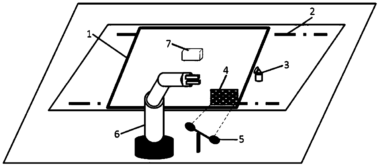
[0004] The purpose of the present invention is to overcome the defects of the prior art, in order to solve the problem that the poor positioning accuracy of the purely mechanical positioning method of the tooling plate cannot meet the high-precision positioning requirements, a method for precise positioning of the tooling plate is proposed. Based on the addition of non-contact machine vision positioning, machine vision positioning is a non-contact real-time measurement method, which can improve the positioning accuracy of the tooling plate, and is not affected by factors such as mechanical wear and tooling plate variables, and works stably Reliable, can carry out high-precision automatic operation on the double-speed chain assembly line tooling board

Method used


Image

  • Accurate positioning method of tooling plate
  • Accurate positioning method of tooling plate
  • Accurate positioning method of tooling plate

Examples


Embodiment Construction

[0024] In order to make the object, technical solution and advantages of the present invention clearer, the present invention will be further described in detail below in conjunction with the accompanying drawings and specific embodiments. It should be understood that the specific embodiments described here are only used to explain the present invention, but not to limit the present invention.

[0025] In order to solve the problem that the poor positioning accuracy of the purely mechanical positioning method of the tooling plate cannot meet the high-precision positioning requirements, the invention adds non-contact machine vision positioning on the basis of pure mechanical positioning, and performs secondary positioning on the tooling plate, and the machine Visual positioning is a non-contact real-time measurement method, which can improve the positioning accuracy of the tooling plate, and is not affected by factors such as mechanical parts wear and tooling plate variables. Th...


PUM


Abstract

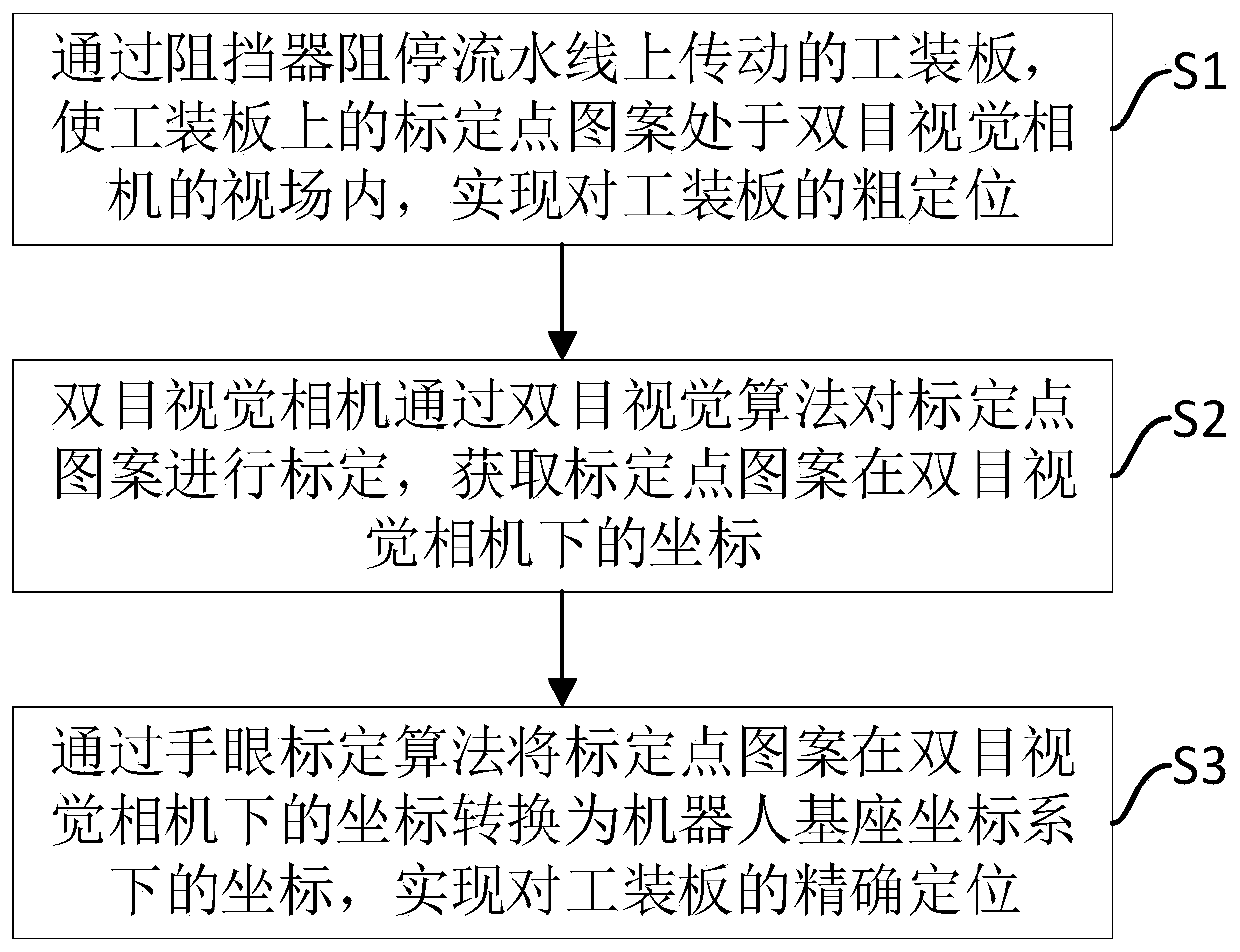
The invention discloses an accurate positioning method of a tooling plate, which comprises the following steps: S1, the tooling plate transmitted on an assembly line is stopped through a stopper, so that a calibration point pattern on the tooling plate is positioned in a view field of a binocular vision camera, and coarse positioning of the tooling plate is realized; S2, the binocular vision camera calibrates the calibration point pattern through a binocular vision algorithm to obtain coordinates of the calibration point pattern under the binocular vision camera; and S3, coordinates of the calibration point pattern are converted under the binocular vision camera into coordinates under a robot base coordinate system through a hand-eye calibration algorithm to realize accurate positioning ofthe tool plate. Secondary positioning of the tooling plate is achieved through cooperation of mechanical positioning and machine vision positioning, the machine vision positioning adopts a non-contact vision real-time measurement mode, the positioning precision can be improved, the influence of mechanical abrasion, tool plate deformation and other factors is avoided, and the production requirement of a modernized automatic production line is met.

Description

technical field [0001] The invention relates to the technical field of industrial visual inspection, in particular to a precise positioning method of a tooling board. Background technique [0002] The double-speed chain assembly line is a form of assembly line widely used in automated production at present. It is mainly used for material transportation in assembly and processing production lines. Its conveying principle is to use the speed-up function of the double-speed chain to make it fast. run, stop at the corresponding operating position by the stopper. The double-speed chain assembly line has very good stability and durability, and is suitable for mass continuous production of products. [0003] In occasions where manual operation or low precision requirements are used, the tooling board of the double-speed chain assembly line is mainly used for rough positioning through the stopper at the front end of the tooling board. etc.), the tooling plate is mainly positioned ...

Claims


Application Information

Patent Timeline
IPC IPC(8): G06T7/00G06T7/73G06T7/80
CPCG06T7/0004G06T7/73G06T7/80G06T2207/10004G06T2207/30164
Inventor 张立文余毅郭同健葛兵陈翱
Owner JIHUA LAB
Why Eureka
Eureka Blog
Learn More